
| Item | Standard Specification | ||||||||||||
|---|---|---|---|---|---|---|---|---|---|---|---|---|---|
| Motor | Capacity Range | 1/2 ~ 10HP 4P | |||||||||||
| Enclosure | Totally Enclosed Fan Cooled Type | ||||||||||||
| Degrees of Protection | IP55 | ||||||||||||
| Voltage and Frequency | - Low Voltage(LT) : 1/2~10HP= 220/380~415V 50Hz, 220/440V 60Hz | ||||||||||||
| - High Voltage(HT) : 5~10HP=380~415V 50Hz. 380~440V 60Hz | |||||||||||||
| Frame Meterial | Steel Plate | ||||||||||||
| Thermal Class | 155 (F) | ||||||||||||
| Rating | S1 (Continuous) | ||||||||||||
| Connection Type | Terminal Block (6 Leads) | ||||||||||||
| Connection Diagram | 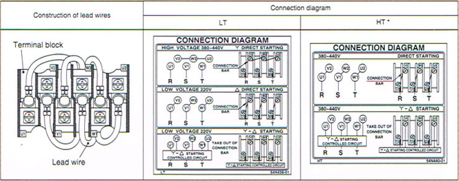 |
||||||||||||
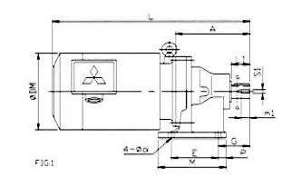
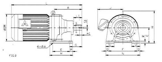
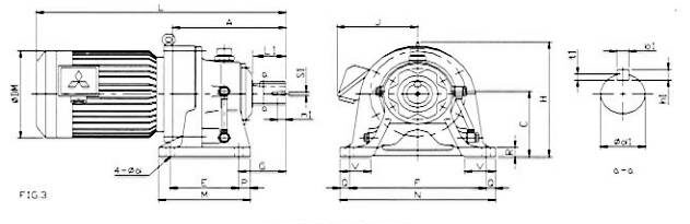
| Cyclo Drive | Lubrication Method | Grease Lubrication (Frame Size 6080~6125) Oil Lubrication (Frame Size 6130~6175) | |||||||||||
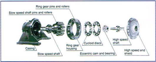
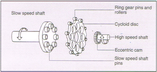
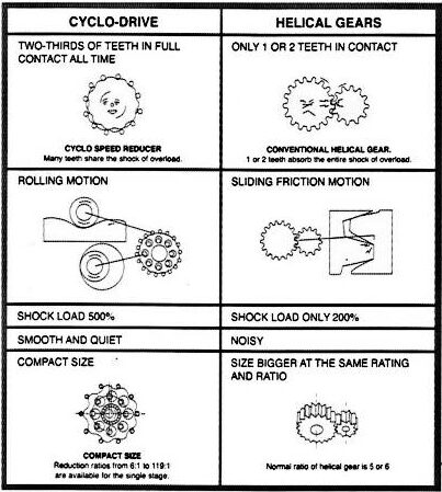
| Speed Reduction Method | Internal planetary gear mechanism with trochoidal curved tooth profile. | ||||||||||||
| Circumstance Condtion | Ambient Temperature | -20˚C~+40˚ | |||||||||||
| Ambient Humidity | 95% RH or less | ||||||||||||
| Above Sea Level | 1000 m.or less | ||||||||||||
| Environment | No bursting / erosive gas or vapor | ||||||||||||
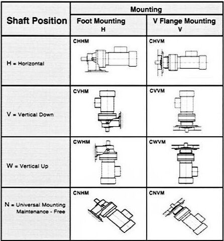
| Method of Mounting | CNHM / CHHM type : Slow speed shaft is in horizontal direction and mount horizontally on foot. | ||||||||||||
*HT can be used only with motors 5HP and above.