Contents Menu
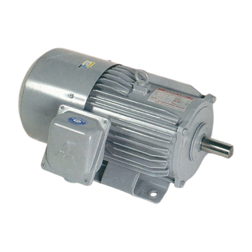
BRAKE MOTOR SUPER LINE J SERIES THREE PHASE
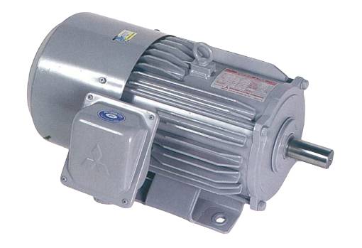
Mitsubishi J Series : Mitsubishi Electric Induction Break Motor provides safety break torque 150% of motor rated torque. The break operation also generates low noise level.
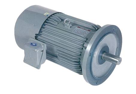
SF-JRB (Horizontal Type, IP55) Horizontal Type Brake Motor
Controllable operating as desires in a blonk of eyes.
Feature
- Low noise level
The noise level when braking operation is proceeded is not over 75dB. - Safety brake
Brake rated damping torque is about 150% of motor rated torque, enhance braking performance. - IP55 degree of protection
Dust and water jet proof structure of both motor and brake body is excellent for operation at outdoor or dusty site.
FEATURE
STRUCTURE AND OPERATION
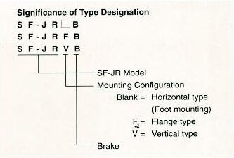
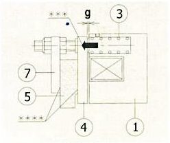
Brake Structrue
| 1 | Fixed core | 9 | Brake lead wire |
| 2 | Coil | 10 | Hub |
| 3 | Braking spring | 11 | Brake cover |
| 4 | Armature | 12 | O-ring |
| 5 | Disc (lining) | 13 | V-ring |
| 6 | Stopper bolt | 14 | Fringer |
| 7 | Brake plate | 15 | Motor bracket |
| 8 | Nut (for adjustment) | 16 | Motor shaft |
The brake’s fixed core (1) and coil (2) are relative to the armature (4) fixed with installation screws to the bracket (15) on the motor’s counter-load side. Braking spring (3) is mounted on the fixed core (1). The disc (5) is installed on the motor shaft (16) via the hub (10). Stopping bolt (6) fixes the brake plate (7) with the nut (8) that is used to adjust the gap (g) between the armature (4) and fixed core (1). The brake cover (11) is fixed to the brake plate (7) with the screw to protect brake body from water. O-ring (12) between brake cover (11) and fixed cored (1) prevent dripping water from seeping inside the brake. V-ring (13) and fringer (14) those rotate with shaft shake the water dripping off before seeping inside the brake and motor.
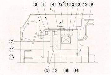
- Releasing Operation
Releasing Operation When electrical current is fed to the coil (2), the electromagnetic force is occurred. This effects the armature (4) overcomes the pressing force of the braking spring (3) and is attracted to the fixed core (1)*. The gap (g) disappears and a clearance is formed between the armature (4) and disc (5)**, freeing the disc (5) and releasing the brake. In this state, the motor shaft (16) can rotate.
Releasing
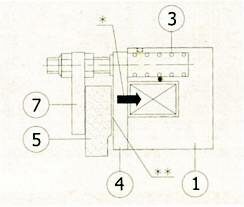
- Braking Operation
Braking
STANDARD SPECIFICATIONS
| Item | Specification | |||||||||
|---|---|---|---|---|---|---|---|---|---|---|
| Motor | Voltage and Frequency | LT : 220/380~415V 50Hz, 220/440V 60Hz (Direct starting) | ||||||||
| Enclosure Construction | Totally enclosed fan cooled type | |||||||||
| Degree of Protection | IP55 | |||||||||
| Coolant System | JC4 | |||||||||
| Rating | Continuous | |||||||||
| Model | Construction | Horizontal | Flange | Vertical | ||||||
| Type | SF-JRB | SF-JRFB | SF-JRVB | |||||||
| Frame No. | 63M ~ 132M | 63M ~ 112M | ||||||||
| Output | 4 Pole | 1/4(0.2) - 10 (7.5) | 1/4(0.2) - 5 (3.7) | |||||||
| HP (kW) | 6 Pole | 1/4(0.2) ~ 7.5 (5.5) | 1/4(0.2) ~ 3 (2.2) | |||||||
| Frame Material | Steel plate | |||||||||
| Insulation Class | F | |||||||||
| Terminal | 6 lead wires with terminal block | |||||||||
| Direction of Rotation | Counter-clockwise (CCW), viewed from shaft-end side | |||||||||
| Circumstance Candition | Ambient temperature | -20˚C - 40˚C | ||||||||
| Ambient humidity | 95% RH or less | |||||||||
| Above sea level | 1000m. or less | |||||||||
| Environment | No bursting/erosive gas or vapor | |||||||||
| Coating Color | Rayton N5.5 (Gray) | |||||||||
| Standard | IEC 34-1, JIS C 4004, etc. | |||||||||
| Brake | Damping System | Non-excited damping type (spring damping type) | ||||||||
| Damping Torque | 2-75 N.m (150%) | |||||||||
| Voltage and Frequency | AC 220V 50Hz, 220V 60Hz (brake with rectifier) | |||||||||
| Insulation Class | F | |||||||||
| Mechanical life | More than 1 million operations | |||||||||
| Standard | TES 1111 | |||||||||
BRAKE CHARACTERISTICS
| Brake Type | Rated damping torque (N•m) | Allowable damping equivalent (kJ/mln) | Electromagnetic characteristic (20°C) | Electromagnetic | Brake Motor GD2* | ||||
|---|---|---|---|---|---|---|---|---|---|
| stroke | (kg-m²) | ||||||||
| Input (W) | Current (DC A) | Initial (mm) | Adjustable limit (mm) | 4 Pole | 6 Pole | ||||
| TB-2 | 2 | 2.3 | 23 | 0.19 | 0.15 | 0.4 | 0.0041 | ||
| TB-4 | 4 | 2.9 | 26 | 0.20 | 0.15 | 0.4 | 0.0063 | ||
| TB-7.5 | 7.5 | 3.2 | 40 | 0.26 | 0.15 | 0.5 | 0.011 | ||
| TB-15 | 15 | 5.1 | 38 | 0.33 | 0.2 | 0.5 | 0.031 | ||
| TB-22 | 22 | 7.2 | 43 | 0.37 | 0.2 | 0.5 | 0.028 | 0.034 | |
| TB-37 | 37 | 10.1 | 55 | 0.50 | 0.2 | 0.55 | 0.059 | 0.068 | |
| TB-75 | 132S | 75 | 11.1 | 250/17** | 2.2/0.55** | 0.25 | 1.2 | 0.096 | 0.14 |
| 132M | 0.14 | 0.19 | |||||||
* Brake motor GD² includes motor driven shait GD² and brake GD².
** The first digit is the impulse value and the second digit is the steady state value.
SF-JRB 63M~132M
Horizontal Type Brake Motor
SF-JRB 3HP 4P 100L
Fig.1
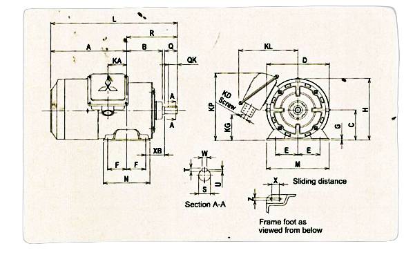
Fig.2
| Model | Frame No. | Output HP(kW) | Brake Type | Fig. | Motor | ||||||||||||||||||
|---|---|---|---|---|---|---|---|---|---|---|---|---|---|---|---|---|---|---|---|---|---|---|---|
| 4 Pole | 6 Pole | A | B | C* | D | E | F | G | H | I | J | K | L | M | ML | N | X | XB | Z | ||||
| SF-JRB | 63M | 1/4 (0.2) | - | TB-2 | 1 | 173 | 73.6 | 63 | 128 | 50 | 40 | 2.3 | 126.9 | - | - | - | 276 | 135 | - | 100 | 12 | 40 | 7 |
| 71M | 1/2 (0.4) | 1/4 (0.2) | TB-4 | 178.5 | 83 | 71 | 150 | 56 | 45 | 3.2 | 145.6 | - | - | - | 298.5 | 148 | - | 110 | 18 | 45 | 7 | ||
| 80M | 1 (0.75) | 1/2 (0.4) | TB-7.5 | 191 | 98 | 80 | 168 | 62.5 | 50 | 3.2 | 161.6 | - | - | - | 331 | 160 | - | 125 | 15 | 50 | 9 | ||
| 90L | 2(1.5) | 1 (0.75) | TB-15 | 218.5 | 117 | 90 | 189 | 70 | 62.5 | 4 | 182.6 | - | - | - | 387 | 175 | - | 150 | 15 | 56 | 9 | ||
| 100L | 3 (2.2) | 2(1.5) | TB-22 | 2 | 250 | 131 | 100 | 213 | 80 | 70 | 6.5 | 203.5 | 230 | 40 | 45 | 443 | 200 | 212 | 180 | 4 | 63 | 12 | |
| 112M | 5 (3.7) | 3 (2.2) | TB-37 | 262 | 138 | 112 | 232 | 95 | 70 | 6.5 | 226 | 253 | 40 | 45 | 462 | 230 | 242 | 180 | 4 | 70 | 12 | ||
| 132S | 7.5 (5.5) | 5 (3.7) | TB-75 | 287.5 | 155 | 132 | 272 | 108 | 70 | 6.5 | 265 | 288 | 40 | 45 | 526.5 | 256 | 268 | 180 | 4 | 89 | 12 | ||
| 132M | 10 (7.5) | 7.5 (5.5) | TB-75 | 306.5 | 174 | 132 | 272 | 108 | 89 | 6.5 | 265 | 288 | 40 | 45 | 564.5 | 256 | 268 | 218 | 4 | 89 | 12 | ||
* The perpendicular variation of tolerance for the shaft center is -0.5
| Frame No. | Terminal Box | Shaft End | Bearing No. | Approx. Weight (kg) | ||||||||||||
|---|---|---|---|---|---|---|---|---|---|---|---|---|---|---|---|---|
| KA | KG | KD | KL | KP** | Q | QK | R | S | T | U | W | Drive End | Opposite | 4 Pole | 6 Pole | |
| 63M | 38.4 | 69 | PF 1/2 | 153 | 175 | 23 | 20 | 103 | 11h6 | 4 | 2.5 | 4 | 6201ZZ | 6201ZZ | 8 | - |
| 71M | 44.5 | 53 | PF 1/2 | 165 | 168 | 30 | 25 | 120 | 14j6 | 5 | 3 | •5 | 6202ZZ | 6202ZZ | 11 | 11 |
| 80M | 39.5 | 32 | PF 3/4 | 167 | - | 40 | 32 | 140 | 19j6 | 6 | 3.5 | 6 | 6204ZZ | 6204ZZ | 15 | 15 |
| 90L | 53 | 46 | PF 3/4 | 180 | - | 50 | 40 | 168.5 | 24j6 | 7 | 4 | 8 | 6205ZZ | 6205ZZ | 25 | 24 |
| 100L | 65 | 59 | PF 3/4 | 192 | - | 60 | 45 | 193 | 28j6 | 7 | 4 | 8 | 6206ZZ | 6205ZZ | 31 | 33 |
| 112M | 69 | 74 | PF 3/4 | 203 | - | 60 | 45 | 200 | 28j6 | 7 | 4 | 8 | 6207ZZ | 6206ZZ | 43 | 45 |
| 132S | 75 | 84 | PF1 | 242 | - | 80 | 63 | 239 | 38k6 | 8 | 5 | 10 | 6308ZZ | 6207ZZ | 58 | 60 |
| 132M | 94 | 84 | PF1 | 242 | - | 80 | 63 | 258 | 38k6 | 8 | 5 | 10 | 6308ZZ | 6207ZZ | 69 | 72 |
** This dimension is for model which KP>H only
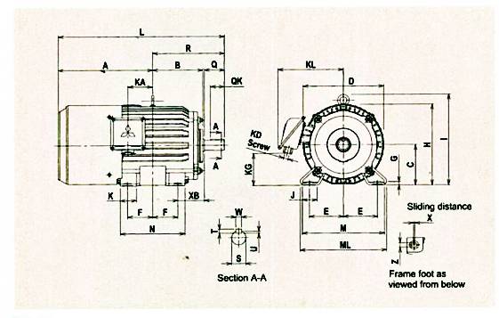
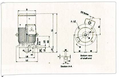
SF-JRFB 63M~123M
Flange Type Brake Motor
SF-JRFB 10HP 132M
Fig.3
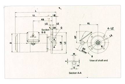
Fig.4
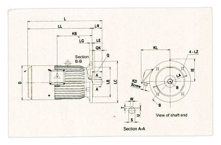
| Model | Frame No. | Output HP(kW) | Brake Type | Fig. | Motor | ||||||||||
|---|---|---|---|---|---|---|---|---|---|---|---|---|---|---|---|
| 4 Pole | 6 Pole | D | IE | LA | LB | LC | LE | LG | LL | LZ | L | ||||
| SF-JRFB | 63M | 1/4 (0.2) | - | TB-2 | 3 | 128 | - | 130 | 110j6 | 160 | 3.5 | 10 | 259.5 | 10 | 282.5 |
| 71M | 1/2 (0.4) | 1/4 (0.2) | TB-4 | 150 | - | 130 | 110j6 | 160 | 3.5 | 10 | 279 | 10 | 309 | ||
| 80M | 1 (0.75) | 1/2 (0.4) | TB-7.5 | 168 | - | 165 | 130j6 | 200 | 3.5 | 12 | 295 | 12 | 335 | ||
| 90L | 2(1.5) | 1 (0.75) | TB-15 | 189 | - | 165 | 130j6 | 200 | 3.5 | 12 | 364 | 12 | 414 | ||
| 100L | 3 (2.2) | 2(1-5) | TB-22 | 4 | 213 | 130 | 215 | 180j6 | 250 | 4 | 16 | 398 | 14.5 | 458 | |
| 112M | 5(3.7) | 3 (2.2) | TB-37 | 232 | 141 | 215 | 180j6 | 250 | 4 | 16 | 432 | 14.5 | 492 | ||
| 132S | 7.5 (5.5) | 5(3.7) | TB-75 | 272 | 156 | 265 | 230j6 | 300 | 4 | 20 | 468.5 | 14.5 | 548.5 | ||
| 132M | 10(7.5) | 7.5 (5.5) | TB-75 | 272 | 156 | 265 | 230j6 | 300 | 4 | 20 | 506.5 | 14.5 | 586.5 | ||
| Model | Frame No. | Terminal Box | Shaft End | Bearing No. | Approx. Weight (kg) | |||||||||||
|---|---|---|---|---|---|---|---|---|---|---|---|---|---|---|---|---|
| KB | KD | KL | KP* | LR | Q | QK | S | T | U | W | Drive End | Opposite | 4 Pole | 6 Pole | ||
| SF-JRFB | 63M | 125 | PF 1/2 | 153 | 112 | 23 | 23 | 20 | 11h6 | 4 | 2.5 | 4 | 6201ZZ | 6201ZZ | 9 | - |
| 71M | 145 | PF 1/2 | 165 | 97 | 30 | 30 | 25 | 14j6 | 5 | 3 | 5 | 6202ZZ | 6202ZZ | 12 | 12 | |
| 80M | 143.5 | PF 3/4 | 167 | - | 40 | 40 | 32 | 19j6 | 6 | 3.5 | 6 | 6204ZZ | 6204ZZ | 18 | 18 | |
| 90L | 198.5 | PF 3/4 | 180 | - | 50 | 50 | 40 | 24j6 | 7 | 4 | 8 | 6205ZZ | 6205ZZ | 27 | 26 | |
| 100L | 213 | PF 3/4 | 192 | - | 60 | 60 | 45 | 28j6 | 7 | 4 | 8 | 6206ZZ | 6205ZZ | 35 | 37 | |
| 112M | 239 | PF 3/4 | 203 | - | 60 | 60 | 45 | 28j6 | 7 | 4 | 8 | 6207ZZ | 6206ZZ | 47 | 49 | |
| 132S | 256 | PF1 | 242 | - | 80 | 80 | 63 | 38k6 | 8 | 5 | 10 | 6308ZZ | 6207ZZ | 66 | 68 | |
| 132M | 294 | PF1 | 242 | - | 80 | 80 | 63 | 38k6 | 8 | 5 | 10 | 6308ZZ | 6207ZZ | 77 | 80 | |
* This dimension is for model which KP>LC/2 only
SF-JRVB 63M~112M
Vertical Type Brake Motor
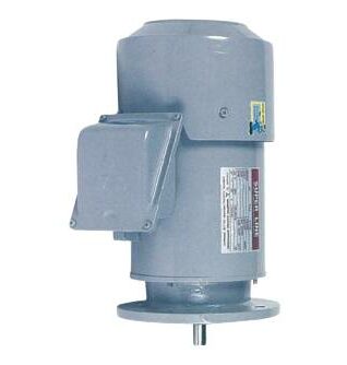
SF-JRVB 12HP 71M
Fig.5
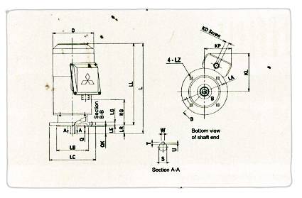
Fig.6
| Model | Frame No. | Output HP(kW) | Brake Type | Fig. | Motor | ||||||||||
|---|---|---|---|---|---|---|---|---|---|---|---|---|---|---|---|
| 4 Pole | 6 Pole | D | IE | LA | LB | LC | LE | LG | LL | LZ | L | ||||
| SF-JRVB | 63M | 1/4 (0.2) | - | TB-2 | 5 | 128 | - | 130 | 110j6 | 160 | 3.5 | 10 | 259.5 | 10 | 282.5 |
| 71M | 1/2 (0.4) | 1/4 (0.2) | TB-4 | 150 | - | 130 | 110j6 | 160 | 3.5 | ,10 | 279 | 10 | 309 | ||
| 80M | 1 (0.75) | 1/2 (0.4) | TB-7.5 | 168 | - | 165 | 130j6 | 200 | 3.5 | 12 | 295 | 12 | 335 | ||
| 90L | 2(1.5) | 1 (0.75) | TB-15 | 189 | - | 165 | 130j6 | 200 | 3.5 | 12 | 364 | 12 | 414 | ||
| 100L | 3 (2.2) | 2(1-5) | TB-22 | 6 | 213 | 130 | 215 | 180j6 | 250 | 4 | 16 | 398 | 14.5 | 458 | |
| 112M | 5 (3.7) | 3 (2.2) | TB-37 | 232 | 141 | 215 | 180j6 | 250 | 4 | 16 | 432 | 14.5 | 492 | ||
| Model | Frame No. | Terminal Box | Shaft End | Bearing No. | Approx. Weight (kg) | |||||||||||
|---|---|---|---|---|---|---|---|---|---|---|---|---|---|---|---|---|
| KD | KG | KL | KP* | LR | Q | QK | S | T | U | W | Drive End | Opposite | 4 Pole | 6 Pole | ||
| SF-JRVB | 63M | PF 1/2 | 42 | 144 | 133 | 23 | 23 | 20 | 11h6 | 4 | 2.5 | 4 | 6201ZZ | 6201ZZ | 9 | - |
| 71M | PF 1/2 | 62 | 159 | 120 | 30 | 30 | 25 | 14j6 | 5 | 3 | 5 | 6202ZZ | 6202ZZ | 12 | 12 | |
| 80M | PF 3/4 | 61 | 163 | - | 40 | 40 | 32 | 19j6 | 6 | 3.5 | 6 | 6204ZZ | 6204ZZ | 18 | 18 | |
| 90L | PF 3/4 | 116 | 176 | - | 50 | 50 | 40 | 24j6 | 7 | 4 | 8 | 6205ZZ | 6205ZZ | 27 | 26 | |
| 100L | PF 3/4 | 130 | 189 | - | 60 | 60 | 45 | 28j6 | 7 | 4 | 8 | 6206ZZ | 6205ZZ | 35 | 37 | |
| 112M | PF 3/4 | 156 | 199 | - | 60 | 60 | 45 | 28j6 | 7 | 4 | 8 | 6207ZZ | 6206ZZ | 47 | 49 | |
* This dimension is for model which KP>LC/2 only
BRAKE MOTOR CHARACTERISTIC
LT (220/380~415V 50Hz, 220/440V 60Hz)
SF-JRB / SF-JRFB 63M~132M
SF-JRVB 63M~112M
| Pole | Output | Frame No. | Brake Type | Full Load Current(A) / Full Load Revolution(r/min) | |||||
|---|---|---|---|---|---|---|---|---|---|
| HP | kW | 220V 50Hz | 380V 50Hz | 415V 50Hz | 220V 60Hz | 440V 60Hz | |||
| 4 | 1/4 | 0.2 | 63M | TB-2 | 1.11 / 1430 | 0.64 / 1430 | 0.69 / 1440 | 0.97 / 1730 | 0.61 / 1750 |
| 1/2 | 0.4 | 71M | TB-4 | 2 / 1410 | 1.15 / 1410 | 1.2 / 1430 | 1.8 / 1700 | 1 / 1730 | |
| 1 | 0.75 | 80M | TB-7.5 | 3.3 / 1400 | 1.9 / 1400 | 1.95 / 1410 | 3 / 1700 | 1.7 / 1720 | |
| 2 | 1.5 | 90L | TB-15 | 5.9 / 1430 | 3.4 / 1430 | 3.4 / 1440 | 5.5 / 1710 | 3.1 / 1730 | |
| 3 | 2.2 | 100L | TB-22 | 8.7 / 1420 | 5 / 1420 | 4.9/ 1430 | 8.5 / 1710 | 4.6 / 1730 | |
| 5 | 3.7 | 112M | TB-37 | 13.7 / 1420 | 7.9 / 1420 | 7.7 / 1430 | 13.5 / 1710 | 7.2 / 1730 | |
| 7.5 | 5.5 | 132S | TB-75 | 20.4 / 1430 | 11.8 / 1430 | 11.1 / 1440 | 19.9 / 1720 | 10.3 / 1740 | |
| 10 | 7.5 | 132M | TB-75 | 27 / 1430 | 15.4 / 1430 | 14.6 / 1440 | 26 / 1720 | 13.5 / 1740 | |
| 6 | 1/4 | 0.2 | 71M | TB-4 | 1.21 / 920 | 0.7 / 920 | 0.7 / 930 | 1.12 / 1100 | 0.65 / 1120 |
| 1/2 | 0.4 | 80M | TB-7.5 | 2.25 / 920 | 1.3 / 920 | 1.3 / 930 | 2.1 / 1100 | 1.2 / 1110 | |
| 1 | 0.75 | 90L | TB-15 | 3.6 / 940 | 2.1 / 940 | 2.2 / 950 | 3.5 / 1130 | 2 / 1150 | |
| 2 | 1.5 | 100L | TB-22 | 6.6 / 930 | 3.8 / 930 | 3.7 / 940 | 6.2 / 1110 | 3.4 / 1120 | |
| 3 | 2.2 | 112M | TB-37 | 9.5 / 940 | 5.5 / 940 | 5.4 /950 | 9 / 1120 | 5.1 / 1140 | |
| 5 | 3.7 | 132S | TB-75 | 15.2 / 940 | 8.8 / 940 | 8.4 / 950 | 14.2 / 1130 | 7.8 / 1150 | |
| 7.5 | 5.5 | 132M | TB-75 | 22 / 950 | 12.8 / 950 | 13 / 960 | 21 / 1140 | 11.5 / 1150 | |
Connection
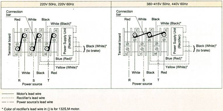
Note : 1. ㅅ- A starting is not allowable.
2. The difference of these 2 cases of connection is only at connection bar connection method.
OEIC STANDARD BRAKE MOTOR STOCK
| ● | In stock | ο | Upon request | - | Unavailable |
|---|
| Pole | Output | Frame No. | Brake Type | Motor Model | |||
|---|---|---|---|---|---|---|---|
| HP | kW | SF-JRB (Horizontal) | SF-JRFB (Flange) | SF-JRVB (Vertical) | |||
| 4 | 1/4 | 0.2 | 63M | TB-2 | ● | ο | ο |
| 1/2 | 0.4 | 71M | TB-4 n | ● | ο | ο | |
| 1 | 0.75 | 80M | TB-7.5 | ● | ο | ο | |
| 2 | 1.5 | 90L | TB-15 | ● | ο | ο | |
| 3 | 2.2 | 100L | TB-22 | ● | ο | ο | |
| 5 | 3.7 | 112M | TB-37 | ● | ο | ο | |
| 7.5 | 5.5 | 132S | TB-75 | ● | ο | - | |
| 10 | 7.5 | 132M | TB-75 | ● | ο | - | |
| 6 | 1/4 | 0.2 | 71M | TB-4 | ο | ο | ο |
| 1/2 | 0.4 | 80M | TB-7.5 | ο | ο | ο | |
| 1 | 0.75 | 90L | TB-15 | ο | ο | ο | |
| 2 | 1.5 | 100L | TB-22 | ο | ο | ο | |
| 3 | 2.2 | 112M | TB-37 | ο | ο | ο | |
| 5 | 3.7 | 132S | TB-75 | ο | ο | - | |
| 7.5 | 5.5 | 132M | TB-75 | ο | ο | - | |