Contents Menu
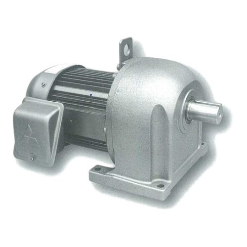
GEARED MOTOR MODEL GM-D
GEARED MOTOR MODEL GM-D The results of advanced technologies, High-performance geared motor, applicable to a wide range of industrial fields Geared motor that is indispensable as driving source-for FA and exhibit their performance in a wide range of industrial fields, ranging from transportation equipment to food proc cessing equipment.
Introduction
The results of advanced technologies, High-performance geared motor, applicable to a wide range of industrial fields Geared motor that is indispensable as driving source-for FA and exhibit their performance in a wide range of industrial fields, ranging from transportation equipment to food proc cessing equipment. Mitsubishi geared motor is highly appriciated for their high capabilities, low noise level and compact & durable body that appropriate to the FA age.
Features
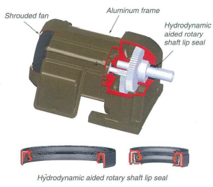
- Sealing
Hydrodynamic aided rotary shaft lip seals are provided for high-frequency driving to improve sealing quality up to 100 times in comparison with before.
- Compact and lightweight
High performance cooling structure with cembination of aluminum alloy motor frame and shrouded cooling fan, Integrated with RGC (Round-bar Gear Cutting: gear cutting after heat treatment) technology and precision cutting, make the product to be compact and lightweight, suitable for install with limited space machine.
- Low noise
From RGC technology and the precision cutting to pinion gear (1st gear) and 2nd gear grinding, realized to low noise operation.
- Ecology
Has no 6 hazardous restricted substances which defined in European RoHS directive. Metallic silver and metallic grey painting are applied for environment.
- Easy use
By Tapped shaft end and extremely safe terminal box (terminal base), casier sprocket fix and wiring. Developed grease seal capability by improved construction, dimension and oil seal material.
- Motor with brake is available
With totally enclosed brake structure, brake noise and abrasion powder is only scattering inside brake cover for environment. Provided with up to 150% brake torque to support elevator usage Easier wiring with built-in rectifier inside terminal block.
- Rich variation
Various gear ratio line-up from 1/3-1/1200 in parallel shaft. Variations are as of safety-plus explosion proof, pressure-proof,
high efficiency motor, motor for two-level parking lot, with CE standard. (Please consult us before order)
Product Code nomenclature
| GM | |
|---|---|
| Geared Motor | |
| D |
||
|---|---|---|
| D : D Series (SF 1.4) DD : DD Series (SF 2.0) |
||
| F |
||
|---|---|---|
| Blank : Horizontal type F : Flange type ** |
||
| B | ||
|---|---|---|
| Blank : Without brake B : With brake ** |
||
*The DD series is for heavy shock loads. (See Table 1)
**Additional model (See standard Specification in Table 3 , page 2)
Ordering
When making an order or an inquiry, please prepare these following basic specifications.
| Model name |
GM-D
| Output |
0.75 kW
| Gear ratio (or speed) |
1/30 (or 50 r/min)
| Voltage |
220/380 V
| Frequency |
50 Hz
| Special specifications |
Outdoor type
Load condition for service factor selection
Table 1 : Load condition
| Service factor |
Load condition | |||||||||||
|---|---|---|---|---|---|---|---|---|---|---|---|---|
| 3 hrs./day discontinuous operation |
3 ̴ 10 hrs./day continuous operation |
Over 10 hrs./day continuous operation |
Applied model |
|||||||||
| 1.4 | Heavy shock load | Moderate shock load | Constant or low shock | GM-D | ||||||||
| 2 | - | Heavy shock load | Moderate shock load | GM-DD | ||||||||
Stock & delivery (Gear ratio : 1/3 ~ 1/200)
Table 2: Gear size and stock & delivery
Standard (see Table 3)――――――――――――――――――――――――――――――――――Additional Model
| Output shaft rotation speed (r/min) |
50Hz | 500 | 300 | 150 | 100 | 75 | 60 | 50 | 37.5 | 30 | 25 | 18.8 | 15 | 12.5 | 9.4 | 7.5 | |
|---|---|---|---|---|---|---|---|---|---|---|---|---|---|---|---|---|---|
| 60Hz | 600 | 360 | 180 | 120 | 90 | 72 | 60 | 45 | 36 | 30 | 22.5 | 18 | 15 | 11.3 | 9 | ||
| Gear ratio | ⅟₃ | ⅟₅ | ⅟₁₀ | ⅟₁₅ | ⅟₂₀ | ⅟₂₅ | ⅟₃₀ | ⅟₄₀ | ⅟₅₀ | ⅟₆₀ | ⅟₈₀ | ⅟₁₀₀ | ⅟₁₂₀ | ⅟₁₆₀ | ⅟₂₀₀ | ||
| Output (kW) | Without brake | 0.4 | ⃝D | ●D | ●D | ●D | ●D | ◌D | ●D | ●D | ⃝D | ⃝G | ⃝G | ∆G | ∆J | ∆J | ∆J |
| 0.75 | ⃝F | ●F | ●F | ●F | ●F | ⃝F | ●F | ●F | ⃝G | ⃝J | ⃝J | ∆J | ∆L | ∆L | ∆L | ||
| 1.5 | ⃝H | ●H | ●H | ●H | ●H | ⃝H | ●H | ●J | ⃝J | ⃝L | ⃝L | ∆L | ∆M | ∆M | ∆M | ||
| 2.2 | ⃝J | ●J | ●J | ●J | ●J | ⃝J | ●J | ●L | ⃝L | ⃝M | ⃝M | ∆M | ∆N | ∆N | ∆N | ||
| 3.7 | ⃝L | ●L | ●L | ●L | ●L | ⃝L | ●L | ●M | ⃝M | ⃝N | ⃝N | ∆N | |||||
| 5.5 | ⃝M | ●M | ●M | ●M | ●M | ⃝M | ●M | ●N | ⃝N | ||||||||
| 7.5 | ⃝M | ●M | ●M | ●M | ●M | ⃝N | ●N | ||||||||||
| With brake | 0.4 | ⃝D | ⃝D | ⃝D | ⃝D | ⃝D | ⃝D | ⃝D | ⃝D | ⃝D | ⃝G | ⃝G | ∆G | ||||
| 0.75 | ⃝F | ⃝F | ⃝F | ⃝F | ⃝F | ⃝F | ⃝F | ⃝G | ⃝G | ⃝J | ⃝J | ∆J | |||||
| 1.5 | ⃝H | ⃝H | ⃝H | ⃝H | ⃝H | ⃝H | ⃝H | ⃝J | ⃝J | ⃝L | ⃝L | ∆L | |||||
| 2.2 | ⃝J | ⃝J | ⃝J | ⃝J | ⃝J | ⃝J | ⃝J | ⃝L | ⃝L | ⃝M | |||||||
| 3.7 | ⃝L | ⃝L | ⃝L | ⃝L | ⃝L | ⃝L | ⃝L | ⃝M | ⃝M | ⃝N | |||||||
| 5.5 | ⃝M | ⃝M | ⃝M | ⃝M | ⃝M | ⃝M | ⃝M | ⃝N | ⃝N | ||||||||
| 7.5 | ⃝M | ⃝M | ⃝M | ⃝M | ⃝M | ⃝N | ⃝N | ||||||||||
• In stock
⃝ Upon request and delivery within 60 days
∆ Upon request and delivery within 90 days
Remarks: For more than 1/200 gear ratio, please consult us before order
Standard Specifications
Table 3: Standard (GM-D 0.4kW~7.5kW Gear Ratio 1/3~1/60 220/380V 50Hz)
| Item | Standard Specifications | |||||||||
|---|---|---|---|---|---|---|---|---|---|---|
| Output | 0.4, 0.75, 1.5, 2.2, 3.7,5.5, 7.5kW | |||||||||
| Pole | 4 | |||||||||
| Phase | 3 phase | |||||||||
| Voltage / Frequency | 220V 50Hz, 380V 50Hz | |||||||||
| Gear Ratio | 1/3~ 1/60 (5.5kW:1/3~1/50,7.5kW:1/3~1/30) | |||||||||
| Rating | Continuous | |||||||||
| Thermal class | E (0.4~0.75kW), B (1.5~7.5kW) | |||||||||
| starting | Direct | |||||||||
| Casting Construction | Totally-enclosed fan-cooled | |||||||||
| Protective construction | Indoor (IP 44) | |||||||||
| Mounting | Foot mount | |||||||||
| Mounting Direction | Grease lubrication type : Universal direction / Oil lubrication type : Limited (see page 3) | |||||||||
| Ambient temperature | -15 ~ +40 *C (No freezing) | |||||||||
| Ambient humidity | 90% RH or less | |||||||||
| Elevation | up to 1,000 meters above sea level | |||||||||
| Vibration | 4.9m/s2 or less constantly,9.8m/s2 or less instantaneously | |||||||||
| Lubrication | 0.4~3.7 kW : Grease lubrication (Pyroknock Universal#000) 2.2kW 1/60 3.7kW 1/40~1/60, 5.5,7.5kW : Oil lubrication (no filled oil from factory) | |||||||||
| Service Factor | GM-D : 1.4 (reduction gear) | |||||||||
| Conformative standard | JEC 2137 | |||||||||
| Paint | Metalic gray (Munsell N4.5) | |||||||||
| Accessories | Shaft end key (JIS B 1301-1996) | |||||||||
Wiring and output shaft rotation direction
(1) Connect power supply to terminal as shown in Table 4. To rotate in opposit direction, swap any pair of wires (from R, S, and T).
(2) Output shaft rotation direction is as shown in Table 5. (when power supply is connected as shown in Table 4)
Table 4: Standard wiring
Table 4: Standard wiring
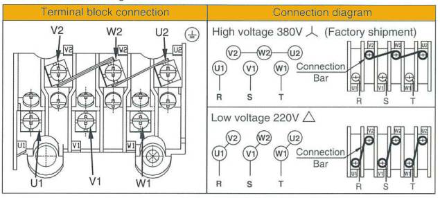
Table 5 : Output shaft rotation direction
| Output (kW) |
Gear ratio | Step No. of Gear |
Rotation direction | ||
|---|---|---|---|---|---|
| 0.4 | 1/3 ~ 1/50 | 2 | Counterclockwise | ||
| 1/60 ~ 1/200 | 3 | Clockwise | |||
| 0.75 | 1/3 ~ 1/30 | 2 | Counterclockwise | ||
| 1/40 ~ 1/200 | 3 | Clockwise | |||
| 1.5 | 1/3 ~ 1/30 | 2 | Counterclockwise | ||
| 1/40 ~ 1/200 | 3 | Clockwise | |||
| 2.2 | 1/3 ~ 1/30 | 2 | Counterclockwise | ||
| 1/40 ~ 1/200 | 3 | Clockwise | |||
| 3.7 | 1/3 | 3 | Clockwise | ||
| 1/5 ~ 1/30 | 2 | Counterclockwise | |||
| 1/40 ~ 1/200 | 3 | Clockwise | |||
| 5.5 | 1/3 ~ 1/30 | 2 | Counterclockwise | ||
| 140, 1/50 | 3 | Clockwise | |||
| 7.5 | 1/3 ~ 1/30 | 2 | Counterclockwise | ||
Lubrication details
(1) For grease lubrication type, grease is filled from factory. For ambient temperature between -15˚C to +40˚C, lithium soap
grease (extreme pressure) NLGI No.000 is applicable. Grease lubrication type can be installed in universal direction.
(2) For the oil lubrication type, no filled oil from factory shipment. Select appropriate oil type and quantity by refer to Table 6-7.
Before operation, oil level must be above red line on oil level gauge. Do not overfill, doing so can cause to leak or overheat.
Allowable inclination for horizontal installation is as shown in Table 8. In case of flange type model, both horizontal or vertical
installation is applicable by swap position of air breather and oil fill plug. (see Fig. 1)
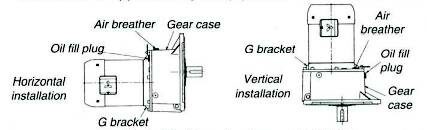
Fig. 1 – Position of parts upon installation
Table 6 Lubrication Quantity)
| Output shaft rotation speed (r/min) |
50Hz | 500 | 300 | 150 | 100 | 75 | 60 | 50 | 37.5 | 30 | 25 | 18.8 | 15 | 12.5 | 9.4 | 7.5 | |
|---|---|---|---|---|---|---|---|---|---|---|---|---|---|---|---|---|---|
| 60Hz | 600 | 360 | 180 | 120 | 90 | 72 | 60 | 45 | 36 | 30 | 22.5 | 18 | 15 | 11.3 | 9 | ||
| Gear ratio | 1/3 | 1/5 | 1/10 | 1/15 | 1/20 | 1/25 | 1/30 | 1/40 | 1/50 | 1/60 | 1/80 | 1/100 | 1/120 | 1/160 | 1/200 | ||
| GM-D Output (kW) |
0.4 | 0.52 (0.45) | 0.42 (4.5) | 1.0 (0.9) | 2.1 (2.1) | ||||||||||||
| 0.75 | 0.9 (0.8) | 1.0 (0.9) | 2.1 (2.1) | 2.7 (2.5) | |||||||||||||
| 1.5 | 1.5 (1.4) | 2.1 (2.1) | 2.7 (2.5) | 2 (1.6) 4.2 | |||||||||||||
| 2.2 | 2.1 (2.1) | 2.7 (2.5) | 2 (1.6) 4.2 | 3.3 (3) 7 | |||||||||||||
| 3.7 | 3.2 (2.5) | 2 (1.6) 4.2 | 3.3 (3) 7 | ||||||||||||||
| 5.5 | 2 (1.6) 4.2 | 3.3 (3) 7 | |||||||||||||||
| 7.5 | 2 (1.6) 4.2 | 3.3 (3) 7 | |||||||||||||||
| GM-DD Output (kW) |
0.4 | 0.9 (0.8) | 1.0 (0.9) | 2.1 (2.1) | 3.2 (2.5) | ||||||||||||
| 0.75 | 1.5 (1.4) | 2.1 (2.1) | 3.2 (2.5) | 2 (1.6) 4.2 | |||||||||||||
| 1.5 | 2.1 (2.1) | 3.2 (2.5) | 2 (1.6) 4.2 | 3.3 (3) 7 | |||||||||||||
| 2.2 | 3.2 (2.5) | 2 (1.6) 4.2 | 3.3 (3) 7 | ||||||||||||||
| 3.7 | 2 (1.6) 4.2 | 3.3 (3) 7 | |||||||||||||||
| 5.5 | 2 (1.6) 4.2 | 3.3 (3) 7 | |||||||||||||||
Table 8 – Allowable installation inclination
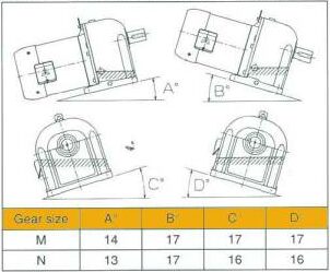
Remark: Please see Table 2, page 2 for gear size
Table 7 - Oil lubrication type
| Ambient temp. | -15 ~ 0 | 0 ~ 40 | |||
|---|---|---|---|---|---|
| JIS | Class ISO VG150 | Class 2 ISO VG220 | |||
| Showa shell oil | Shell omala oil 150 | Shell omala oil 220 | |||
| Nippon oil | Bonnoc M 150 | Bonnoc M 220 | |||
| General oil | General SP gearroll 150 | General SP gearroll 220 | |||
| Esso standard oil | Spaltan EP 150 | Spaltan EP 220 | |||
| Maruzen oil | Swacol SP-150 | Swacol SP-220 | |||
| Mobil oil | Mobi gear 629 | Mobi gear 630 | |||
| Cosmo oil | Cosmogear SE-150 | Cosmogear SE-220 |
Motor Characteristics
Table 9 - Motor characteristics for 0.4kW - 0.75kW
| Output (kW) |
Output shaft rotation speed (r/min) |
Round up gear ratio | Actual gear ratio | Output shaft allowable torque (Nm) | Output shaft allowable overhanging load (N) | Output shaft allowable thrust load (N) | Motor specification |
||||||
|---|---|---|---|---|---|---|---|---|---|---|---|---|---|
| 50Hz | 60Hz | 50Hz | 60Hz | V | Hz | A | |||||||
| 0.4 | 500 | 600 | 1/3 | 1/3.00 | 7.3 | 6.0 | 686 | 50 | 220 380 |
50 50 |
1.9 1.1 |
||
| 300 | 360 | 1/5 | 1/4.95 | 12 | 10 | 784 | 83 | ||||||
| 150 | 180 | 1/10 | 1/9.94 | 24 | 20 | 1180 | 167 | ||||||
| 100 | 120 | 1/15 | 1/14.80 | 36 | 30 | 1370 | 250 | ||||||
| 75 | 90 | 1/20 | 1/19.10 | 46 | 38 | 1570 | 333 | ||||||
| 65 | 72 | 1/25 | 1/25.54 | 62 | 51 | 1670 | 417 | ||||||
| 50 | 60 | 1/30 | 1/30.15 | 73 | 61 | 1810 | 500 | ||||||
| 37.5 | 45 | 1/40 | 1/40.20 | 97 | 81 | 1960 | 500 | ||||||
| 30 | 36 | 1/50 | 1/50.62 | 122 | 102 | 2450 | 500 | ||||||
| 25 | 3 | 1/60 | 1/60.06 | 145 | 121 | 3230 | 700 | ||||||
| 18.8 | 22.5 | 1/80 | 1/81.90 | 198 | 165 | 3580 | 700 | ||||||
| 15 | 18 | 1/100 | 1/102.32 | 253 | 211 | 5000 | 700 | ||||||
| 12.5 | 15 | 1/120 | 1/116.37 | 283 | 236 | 6660 | 1200 | ||||||
| 9.4 | 11.3 | 1/160 | 1/161.84 | 391 | 326 | 6960 | 1200 | ||||||
| 7.5 | 9 | 1/200 | 1/179.82 | 444 | 370 | 8620 | 1200 | ||||||
| 0.75 | 500 | 600 | 1/3 | 1/30.4 | 14 | 11 | 980 | 70 | 220 380 |
50 50 |
3.6 2.1 |
||
| 300 | 360 | 1/5 | 1/4.80 | 22 | 18 | 1180 | 117 | ||||||
| 150 | 180 | 1/10 | 1/9.94 | 45 | 38 | 1760 | 233 | ||||||
| 100 | 120 | 1/15 | 1/14.58 | 66 | 55 | 1960 | 350 | ||||||
| 75 | 90 | 1/20 | 1/19.59 | 89 | 74 | 2650 | 467 | ||||||
| 65 | 72 | 1/25 | 1/25.38 | 115 | 96 | 2790 | 583 | ||||||
| 50 | 60 | 1/30 | 1/27.96 | 127 | 106 | 2990 | 700 | ||||||
| 37.5 | 45 | 1/40 | 1/37.93 | 172 | 143 | 3040 | 700 | ||||||
| 30 | 36 | 1/50 | 1/47.39 | 220 | 183 | 4020 | 700 | ||||||
| 25 | 3 | 1/60 | 1/60.20 | 273 | 227 | 4310 | 1200 | ||||||
| 18.8 | 22.5 | 1/80 | 1/83.72 | 380 | 316 | 5680 | 1200 | ||||||
| 15 | 18 | 1/100 | 1/93.02 | 431 | 359 | 7840 | 1200 | ||||||
| 12.5 | 15 | 1/120 | 1/112.28 | 509 | 424 | 9020 | 1300 | ||||||
| 9.4 | 11.3 | 1/160 | 1/156.07 | 722 | 602 | 9310 | 1300 | ||||||
| 7.5 | 9 | 1/200 | 1/179.17 | 829 | 690 | 13030 | 1300 | ||||||
Table 10 - Motor characteristics for 1.5kW ̴7.5kW
| Output (kW) |
Output shaft rotation speed (r/min) |
Round up gear ratio |
Actual gear ratio |
Output shaft allowable torque (Nm) |
Output shaft allowable overhanging load (N) | Output shaft allowable thrust load (N) |
Motor specification | ||||||
|---|---|---|---|---|---|---|---|---|---|---|---|---|---|
| 50Hz | 60Hz | 50Hz | 60Hz | V | Hz | A | |||||||
| 1.5 | 500 | 600 | 1/3 | 1/2.93 | 27 | 22 | 1320 | 70 | 220 , 380 | 50 , 50 | 6.0 , 3.5 | ||
| 300 | 360 | 1/5 | 1/4.91 | 44 | 37 | 1570 | 117 | ||||||
| 150 | 180 | 1/10 | 1/9.78 | 89 | 74 | 2450 | 233 | ||||||
| 100 | 120 | 1/15 | 1/14.57 | 132 | 110 | 2940 | 350 | ||||||
| 75 | 90 | 1/20 | 1/19.76 | 179 | 149 | 3920 | 467 | ||||||
| 6 | 72 | 1/25 | 1/23.47 | 213 | 177 | 4460 | 583 | ||||||
| 50 | 60 | 1/30 | 1/28.42 | 258 | 215 | 5000 | 700 | ||||||
| 37.5 | 45 | 1/40 | 1/40.67 | 367 | 306 | 5190 | 1200 | ||||||
| 30 | 36 | 1/50 | 1/45.19 | 417 | 347 | 6370 | 1200 | ||||||
| 25 | 30 | 1/60 | 1/56.45 | 512 | 427 | 8820 | 1300 | ||||||
| 18.8 | 22.5 | 1/80 | 1/78.46 | 726 | 605 | 9460 | 1300 | ||||||
| 15 | 18 | 1/100 | 1/90.07 | 833 | 694 | 11960 | 1300 | ||||||
| 12.5 | 15 | 1/120 | 1/114.40 | 1040 | 867 | 18330 | 1400 | ||||||
| 9.4 | 11.3 | 1/160 | 1/162.93 | 1480 | 1230 | 18330 | 1400 | ||||||
| 7.5 | 9 | 1/200 | 1/187.20 | 1700 | 1420 | 18330 | 1400 | ||||||
| 2.2 | 500 | 600 | 1/3 | 1/3.04 | 40 | 34 | 1910 | 120 | 220 , 380 | 50 , 50 | 8.5 , 4.9 | ||
| 300 | 360 | 1/5 | 1/5.00 | 66 | 55 | 2250 | 200 | ||||||
| 150 | 180 | 1/10 | 1/9.98 | 133 | 111 | 3430 | 400 | ||||||
| 100 | 120 | 1/15 | 1/14.52 | 193 | 161 | 3920 | 600 | ||||||
| 75 | 90 | 1/20 | 1/18.92 | 252 | 210 | 5100 | 800 | ||||||
| 60 | 72 | 1/25 | 1/23.19 | 308 | 257 | 5640 | 1000 | ||||||
| 50 | 60 | 1/30 | 1/29.36 | 390 | 325 | 6220 | 1200 | ||||||
| 37.5 | 45 | 1/40 | 1/39.16 | 528 | 440 | 6370 | 1300 | ||||||
| 30 | 36 | 1/50 | 1/44.95 | 606 | 505 | 7840 | 1300 | ||||||
| 25 | 30 | 1/60 | 1/59.51 | 794 | 662 | 14700 | 1400 | ||||||
| 18.8 | 22.5 | 1/80 | 1/84.75 | 1130 | 942 | 14700 | 1400 | ||||||
| 15 | 18 | 1/100 | 1/97.83 | 1300 | 1080 | 16270 | 1400 | ||||||
| 12.5 | 15 | 1/120 | 1/117.45 | 1600 | 1330 | 23520 | 2200 | ||||||
| 9.4 | 11.3 | 1/160 | 1/147.99 | 2010 | 1680 | 23520 | 2200 | ||||||
| 7.5 | 9 | 1/200 | 1/189.39 | 2640 | 2200 | 24300 | 2200 | ||||||
| 3.7 | 500 | 600 | 1/3 | 1/2.95 | 66 | 55 | 2700 | 130 | 220 , 380 | 50 , 50 | 13.2 , 7.6 | ||
| 300 | 360 | 1/5 | 1/4.75 | 106 | 88 | 3190 | 217 | ||||||
| 150 | 180 | 1/10 | 1/9.97 | 222 | 185 | 4900 | 433 | ||||||
| 100 | 120 | 1/15 | 1/14.35 | 321 | 268 | 5590 | 650 | ||||||
| 75 | 90 | 1/20 | 1/20.22 | 460 | 384 | 6960 | 867 | ||||||
| 60 | 72 | 1/25 | 1/25.13 | 572 | 477 | 8870 | 1083 | ||||||
| 50 | 60 | 1/30 | 1/28.41 | 635 | 530 | 10780 | 1300 | ||||||
| 37.5 | 45 | 1/40 | 1/41.13 | 932 | 776 | 10190 | 1400 | ||||||
| 30 | 36 | 1/50 | 1/47.26 | 1070 | 892 | 13430 | 1400 | ||||||
| 25 | 30 | 1/60 | 1/62.12 | 1390 | 1160 | 18330 | 2200 | ||||||
| 18.8 | 22.5 | 1/80 | 1/78.27 | 1750 | 1460 | 18330 | 2200 | ||||||
| 15 | 18 | 1/100 | 1/100.17 | 2290 | 1910 | 21850 | 2200 | ||||||
| 5.5 | 500 | 600 | 1/3 | 1/2.91 | 97 | 81 | 2380 | 140 | 220 , 380 | 50 , 50 | 19.8 , 11.5 | ||
| 300 | 360 | 1/5 | 1/4.89 | 162 | 135 | 4120 | 233 | ||||||
| 150 | 180 | 1/10 | 1/9.51 | 315 | 262 | 6370 | 467 | ||||||
| 100 | 120 | 1/15 | 1/14.05 | 467 | 389 | 8620 | 700 | ||||||
| 75 | 90 | 1/20 | 1/18.63 | 620 | 516 | 9800 | 933 | ||||||
| 60 | 72 | 1/25 | 1/23.22 | 772 | 643 | 11270 | 1167 | ||||||
| 50 | 60 | 1/30 | 1/30.10 | 1000 | 833 | 12740 | 1400 | ||||||
| 37.5 | 45 | 1/40 | 1/38.12 | 1270 | 1060 | 14110 | 2200 | ||||||
| 30 | 36 | 1/50 | 1/48.78 | 1660 | 1380 | 15580 | 2200 | ||||||
| 7.5 | 500 | 600 | 1/3 | 1/2.87 | 130 | 108 | 3920 | 210 | 220 , 380 | 50 , 50 | 27.0 , 15.5 | ||
| 300 | 360 | 1/5 | 1/4.99 | 225 | 187 | 4610 | 350 | ||||||
| 150 | 180 | 1/10 | 1/1.86 | 447 | 373 | 7150 | 700 | ||||||
| 100 | 120 | 1/15 | 1/14.22 | 645 | 537 | 10190 | 1050 | ||||||
| 75 | 90 | 1/20 | 1/19.78 | 897 | 747 | 11560 | 1400 | ||||||
| 60 | 72 | 1/25 | 1/24.20 | 1100 | 971 | 13720 | 1833 | ||||||
| 50 | 60 | 1/30 | 1/27.38 | 1240 | 1030 | 15970 | 2200 | ||||||
Outline dimensions
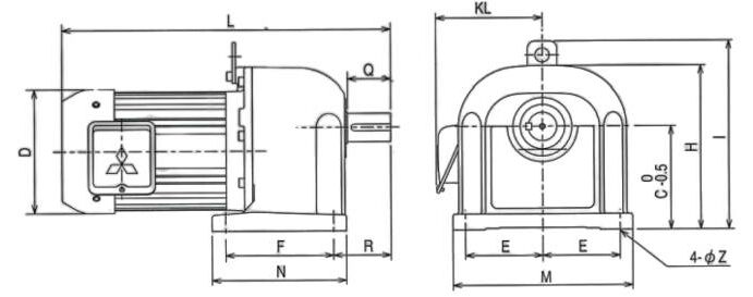
Table 11 - Outline dimensions
| Output (kW) | Gear ratio | Dimension (mm) | Weigth (kg) | ||||||||||||||
|---|---|---|---|---|---|---|---|---|---|---|---|---|---|---|---|---|---|
| L | Q | D | F | R | N | KL | E | M | C | H | I | Z | |||||
| 0.4 | 1/3 ̴1/50 | 289 (341) | 36 | 120 | 85 | 50 | 109 | 121.5 (119) | 75 | 170 | 100 | 160 | - | 10 | 10.5 (12) | ||
| 1/60 | 343 (395) | 50 | 120 | 135 | 65 | 161 | 121.5 (119) | 87.5 | 200 | 125 | 195 | 230 | 12 | 23 (24.5) | |||
| 0.75 | 1/3 ̴1/30 | 361(424) | 50 | 150 | 120 | 65 | 146 | 139 (138) | 87.5 | 200 | 120 | 195 | 230 | 12 | 25.8 (29.4) | ||
| 1/40 , 1/50 | 380 (443) | 50 | 150 | 135 | 65 | 161 | 139 (138) | 87.5 | 200 | 125 | 195 | 230 | 12 | 25.8 (29.4) | |||
| 1/60 | 413 (476) | 60 | 150 | 150 | 80 | 187 | 139 (138) | 107.5 | 250 | 145 | 230 | 265 | 15 | 38.8 (42.4) | |||
| 1.5 | 1/3 ̴1/30 | 418 (490) | 50 | 175 | 115 | 65 | 141 | 149 (148) | 102.5 | 230 | 140 | 227 | 262 | 12 | 35.3 (38.9) | ||
| 1/40 , 1/50 | 457 (529) | 60 | 175 | 150 | 80 | 187 | 149 (148) | 107.5 | 250 | 145 | 230 | 265 | 15 | 44.3 (47.9) | |||
| 1/60 | 484 (556) | 75 | 175 | 170 | 95 | 206 | 149 (148) | 125 | 285 | 170 | 275 | 310 | 15 | 57.3 (60.9) | |||
| 2.2 | 1/3 ̴1/30 | 471 (538) | 60 | 206 | 150 | 80 | 187 | 161 (160) | 107.5 | 250 | 145 | 230 | 265 | 15 | 48.8 (53.5) | ||
| 1/40 , 1/50 | 497 (564) | 75 | 206 | 170 | 95 | 206 | 161 (160) | 125 | 285 | 170 | 275 | 310 | 15 | 61.8 (66.5) | |||
| 1/60 | 540 (607) | 82 | 206 | 200 | 107 | 240 | 161 (160) | 130 | 300 | 195 | 330 | 345 | 19 | 78.2 (82.9) | |||
| 3.7 | 1/3 ̴1/30 | 543 (618) | 75 | 235 | 170 | 95 | 206 | 175 (174) | 125 | 285 | 170 | 275 | 310 | 15 | 82.3 (88.6) | ||
| 1/40 , 1/50 | 584 (659) | 82 | 235 | 200 | 107 | 240 | 175 (174) | 130 | 300 | 195 | 330 | 345 | 19 | 98.7 (105) | |||
| 1/60 | 618 (693) | 9 | 235 | 230 | 120 | 280 | 175 (174) | 150 | 350 | 230 | 380 | 395 | 24 | 134 (140) | |||
| 5.5 | 1/3 ̴1/30 | 637 (717) | 82 | 275 | 200 | 107 | 240 | 194 (194) | 130 | 300 | 195 | 330 | 345 | 19 | 106 (114) | ||
| 1/40 , 1/50 | 671 (751) | 90 | 275 | 230 | 120 | 280 | 194 (194) | 150 | 350 | 230 | 380 | 395 | 24 | 140 (148) | |||
| 7.5 | 1/3 ̴1/50 | 667 (747) | 82 | 275 | 200 | 107 | 240 | 194 (194) | 130 | 300 | 195 | 330 | 345 | 19 | 106 (116) | ||
| 1/5 , 1/30 | 686 (766) | 90 | 275 | 230 | 120 | 280 | 194 (194) | 150 | 350 | 230 | 380 | 395 | 24 | 141 (150) | |||
( ) is for motor with brake
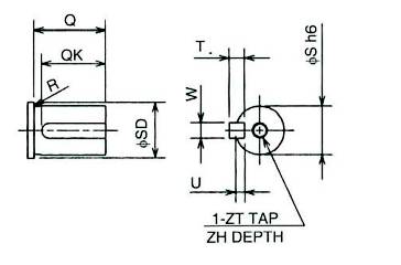
Table 12 - Shaft end dimensions
| Gear size |
Dimension (mm) | ||||||||||
|---|---|---|---|---|---|---|---|---|---|---|---|
| Q | QK | φS h6 | W(key) h9 | U | ZT | ZH | R | φSD | |||
| D | 36 | 32 | 22 | 0 -0.013 | 6 | 0 -0.030 | 3.5 | M8 | 12 | 0.4 | 24 |
| E | 42 | 36 | 28 | 8 | 0 -0.036 | 4 | 29 | ||||
| F | 50 | 45 | 32 | 0 -0.016 | 10 | 5 | 0.8 | 34 | |||
| G | |||||||||||
| H | |||||||||||
| J | 60 | 55 | 40 | 12 | 0 -0.043 | 5 | 1.6 | 45 | |||
| L | 75 | 70 | 48 | 14 | 5.5 | 0.8 | 50 | ||||
| M | 82 | 71 | 55 | 16 | 6 | M10 | 18 | 58 | |||
| N | 90 | 72 | 60 | 18 | 7 | 63 | |||||
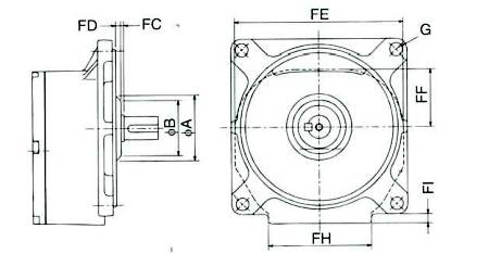
Table 13 - Flange type gear dimensions
| Gear size |
Dimension (mm) | ||||||||
|---|---|---|---|---|---|---|---|---|---|
| φA | φB | FC | FD | FE | FF | G | FH | FI | |
| D | 62 | 44 | 2 | 5.5 | 160 | 62 | 8 | 103 | 8 |
| E | 55 | 53 | 1.5 | 159 | 57 | 10 | 105 | 9 | |
| F | 96 | 67 | 8 | 190 | 77 | 8 | 132 | 16.5 | |
| G | 4 | 188 | 73 | 129 | 13 | ||||
| H | 7 | 216 | 90 | 10 | 156 | 13.5 | |||
| J | 107 | 82 | 10.5 | 234 | 88 | 158 | 6 | ||
| L | 140 | 88 | 5.5 | 270 | 109 | 15 | 183 | 14.5 | |
| M | - | - | 4 | - | 296 | 120 | 20 | 191 | 12 |
| N | 160 | 105 | 5 | 5 | 336 | 135 | 185 | 8 | |
Remarks : Please see Table 2 , page 2 for gear size