Contents Menu
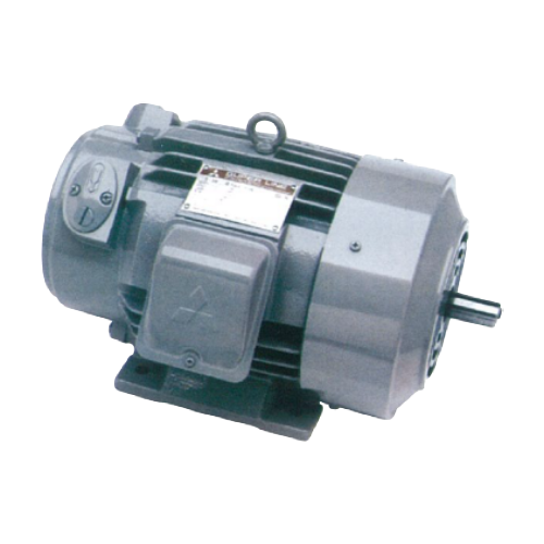
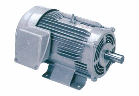
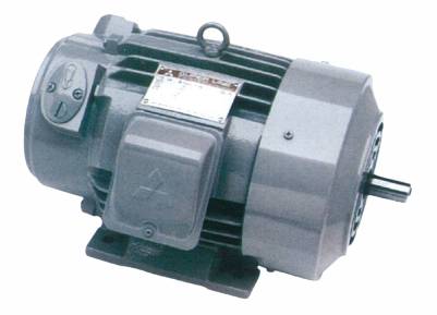
SUPER LINE K SERIES SINGLE PHASE
SUPER LINE K SERIES SINGLE PHASE The variety of type of Single Phase Motor based on JIS (Japanese Industrial Standard) and IEC (International Electrotechnical Commission).
And being positively advanced under technological assistance contract with MITSUBISHI ELECTRIC JAPAN which have an experience for manufacturing motor since 1907.
Feature and Benefits
The variety of type of Single Phase Motor based on JIS (Japanese Industrial Standard) and IEC (International Electrotechnical Commission).
And being positively advanced under technological assistance contract with MITSUBISHI ELECTRIC JAPAN which have an experience for manufacturing motor since 1907.
- Top class of light weighting and down sizing
The best choice of employing steel frame and steel or aluminium bracket (excluding Sl-K Type) that enables light weighting and down sizing motor.
- High efficiency and high torque
Accumulated techniques and CAE (Computer Aided Engineering) analysis that we found steel frame pass through magnetic field then can manufacture high power and save energy of motor.
- Powerful and smooth speed
Due to high efficiency design focused on high acceleration torque and die-cast rotor of rather small moment of inertia enables smooth starting and stopping.
- Low vibration and low noise
Our highly technology equipment, the ample rigidity, precise machining of each part and exact balancing of electrical design which makes MEATH motor have low vibration and low noise.
- High reliability
Improve to highly reliable insulation system by using thermal class E, B, and F to be standard.
- Longer life
Based on selecting the proper bearing size and improving to have highly efficient cooling of bearing housing and steel frame which is greatly affect the longer bearing life.
- Best and reliable design of centrifugal switch
The best design of centrifugal switch from MITSUBISHI ELECTRIC JAPAN that can manufacture in our highly technology equipment which can be reliable.
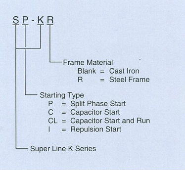
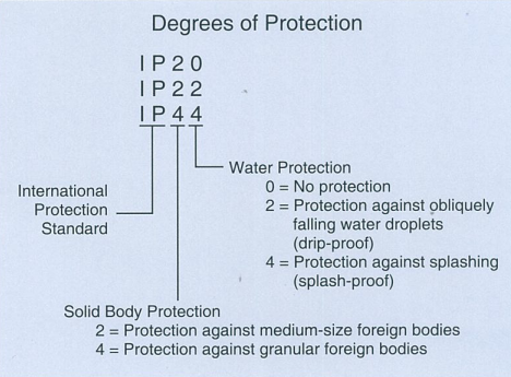
Significance of type designations and degrees of protection for single phase motor
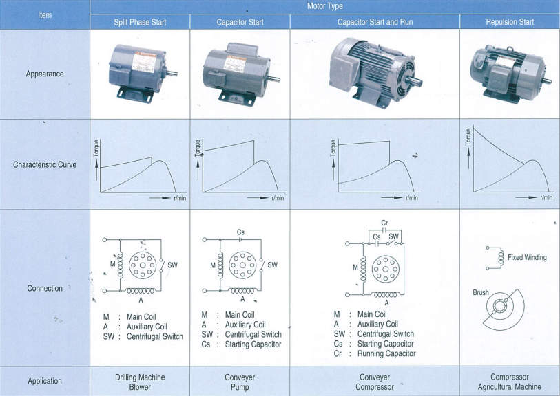
Characteristics and Performance
| Item | SP-KR | SC-KR | SCL-KR | Sl-K | ||||||||||||
|---|---|---|---|---|---|---|---|---|---|---|---|---|---|---|---|---|
| Output (HP) | 1/4 | 1/3 | 1/2 | 1/4 | 1/3 | 1/2 | 1 | 1.5 | 2 | 3 | 5 | 7.5 | 10 | 1/2 | 1 | 1 3/4 |
| Frame No. | A71 | B71 | 80M | A71 | B71 | 80M | 90S | 90L | 100L | 112M | 132S | 132M | 132ML | 100 | 100 | 100 |
| No. of Poles | 4 | 4 | 4 | 4 | 4 | 4 | 4 | 4 | 4 | 4 | 4 | 4 | 4 | 4 | 4 | 4 |
| Thermal Class | E | E | E | E | E | E | B | B | B | B | F | F | F | E | E | E |
| Power Supply | 1 Phase 220V 50Hz | |||||||||||||||
| Full Load Current (A) | 2.8 | 3.1 | 4.8 | 2.6 | 3.1 | 4.3 | 5.2 | 7.9 | 10.4 | 15.1 | 23 | 34 | 44.5 | 3.5 | 7.6 | 12 |
| Full Load Speed (r/min) | 1450 | 1440 | 1440 | 1450 | 1450 | 1430 | 1430 | 1440 | 1450 | 1450 | 1430 | 1450 | 1450 | 1455 | 1460 | 1450 |
| Starting Current (A) | 20 | 26.5 | 34 | 11 | 13.5 | 18.5 | 32 | 44 | 55 | 95 | 107 | 162 | 215 | 12.5 | 25 | 40 |
| Starting Torque (%) | 300 | 290 | 200 | 360 | 302 | 273 | 286 | 244 | 203 | 238 | 232 | 193 | 198 | 615 | 480 | 380 |
| Break Down Torque (%) | 310 | 270 | 293 | 280 | 262 | 390 | 250 | 290 | 239 | 260 | 174 | 195 | 187 | 478 | 290 | 250 |
| Power Supply | 1 Phase 220V 60Hz | |||||||||||||||
| Full Load Current (A) | 2.4 | 2.8 | 4.6 | 2.3 | 2.8 | 3.6 | 4.6 | 7.1 | 9.4 | 13.4 | 23 | 33.5 | 40 | 3.0 | 5.9 | 10.3 |
| Full Load Speed (r/min) | 1740 | 1730 | 1730 | 1740 | 1740 | 1720 | 1720 | 1720 | 1740 | 1740 | 1720 | 1700 | 1740 | 1750 | 1750 | 1740 |
| Starting Current (A) | 19.5 | 26 | 34 | 10.3 | 13.3 | 19.3 | 32 | 45 | 54 | 73 | 102 | 171 | 208 | 13.5 | 27 | 40 |
| Starting Torque (%) | 288 | 232 | 161 | 370 | 303 | 251 | 310 | 285 | 260 | 374 | 174 | 203 | 200 | 670 | 548 | 350 |
| Break Down Torque (%) | 299 | 227 | 251 | 283 | 229 | 327 | 265 | 225 | 245 | 202 | 165 | 210 | 170 | 435 | 265 | 227 |
| Net Weight (kg) | 6.6 | 7.5 | 11 | 6.8 | 7.6 | 11.4 | 15.2 | 18.6 | 23.4 | 32.8 | 45.8 | 60 | 68.2 | 26.4 | 32 | 36.6 |
SP-KR SPLIT PHASE START TYPE
Open-Protected Type, IP 20 Degrees of Protection
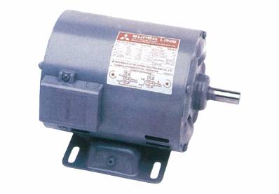
SP-KR 1/4HP 4P A71
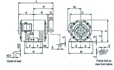
Fig.1
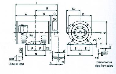
Fig.2
Dimensions(mm)
| Model | Frame No. | Output HP(kW) | Pole | Fig. | Motor | |||||||||||||||||
|---|---|---|---|---|---|---|---|---|---|---|---|---|---|---|---|---|---|---|---|---|---|---|
| A | B | C* | D | E | F | G | H | KA | KD1 | KD2 | KL | L | M | N | X | XB | Z | |||||
| SP-KR | A71 | 1/4(0.2) | 4 | 1 | 92 | 87 | 71 | 131.2 | 56 | 45 | 3.2 | 136.6 | 21.3 | 12 | 12 | 82 | 212 | 148 | 110 | 15 | 45 | 9 |
| B71 | 1/3(0.25) | 4 | 101 | 87 | 71 | 131.2 | 56 | 45 | 3.2 | 136.6 | 30.3 | 12 | 12 | 82 | 221 | 148 | 110 | 15 | 45 | 9 | ||
| 80M | 1/2(0.4) | 4 | 2 | 125 | 97 | 80 | 146.6 | 62.5 | 50 | 3.2 | 153.3 | 44.5 | 12 | 12 | 92 | 265 | 165 | 130 | 10 | 50 | 10 | |
* The perpendicular variation of tolerance for the shaft center is -0.5
| Model | Frame No. | Output HP(kW) | Pole | Fig. | Shaft End | Bering No. | Appoximate Weight (kg) | Appoximate Packing Dimensions (LxWxH) | Packing Weight (kg) | |||||||||||||||||
|---|---|---|---|---|---|---|---|---|---|---|---|---|---|---|---|---|---|---|---|---|---|---|---|---|---|---|
| Q | QK | R | S | T | U | W | Drive End | Opposite | ||||||||||||||||||
| SP-KR | A71 | 1/4(0.2) | 4 | 1 | 30 | 27 | 120 | 14 h6 | - | 1 | - | 6202ZZ | 6201ZZ | 6.6 | 245 x 200 x 184 | 7.0 | ||||||||||
| B71 | 1/3(0.25) | 4 | 30 | 27 | 120 | 14 h6 | - | 1 | - | 6202ZZ | 6201ZZ | 7.5 | 255 x 200 x 184 | 8.0 | ||||||||||||
| 80M | 1/2(0.4) | 4 | 2 | 40 | 28 | 140 | 16 j6 | 5 | 3 | 5 | 6203ZZ | 6202ZZ | 11 | 300 x 200 x 184 | 12 | |||||||||||
SC-KR CAPACITOR START TYPEM
Open-Protected Type, IP 20 Degrees of Protection
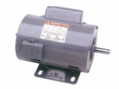
SC-KR 1/2HP 4P 80M
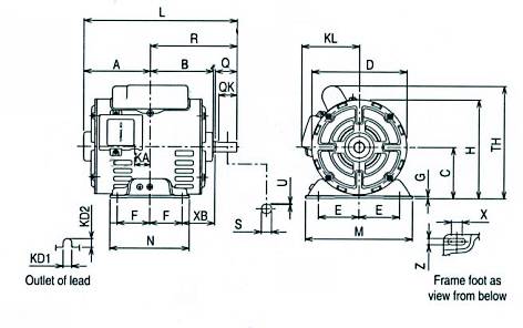
Fig.3
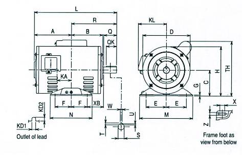
Fig.4
Dimensions(mm)
| Model | Frame No. | Output HP(kW) | Pole | Fig. | Motor | ||||||||||||||||||
|---|---|---|---|---|---|---|---|---|---|---|---|---|---|---|---|---|---|---|---|---|---|---|---|
| A | B | C* | D | E | F | G | H | KA | KD1 | KD2 | KL | L | M | N | X | XB | TH | Z | |||||
| SC-KR | A71 | 1/4(0.2) | 4 | 3 | 92 | 87 | 71 | 131.2 | 56 | 45 | 3.2 | 136.6 | 21.3 | 12 | 12 | 82 | 212 | 148 | 110 | 15 | 45 | 170 | 9 |
| B71 | 1/3(0.25) | 4 | 101 | 87 | 71 | 131.2 | 56 | 45 | 3.2 | 136.6 | 30.3 | 12 | 12 | 82 | 221 | 148 | 110 | 15 | 45 | 167 | 9 | ||
| 80M | 1/2(0.4) | 4 | 4 | 125 | 97 | 80 | 146.6 | 62.5 | 50 | 3.2 | 153.3 | 44.5 | 12 | 12 | 92 | 265 | 165 | 130 | 10 | 50 | 173 | 10 | |
* The perpendicular variation of tolerance for the shaft center is -0.5
| Model | Frame No. | Output HP(kW) | Pole | Fig. | Shaft End | Bering No. | Appoximate Weight (kg) | Appoximate Packing Dimensions (LxWxH) | Packing Weight (kg) | |||||||||||||||||
|---|---|---|---|---|---|---|---|---|---|---|---|---|---|---|---|---|---|---|---|---|---|---|---|---|---|---|
| Q | QK | R | S | T | U | W | Drive End | Opposite | ||||||||||||||||||
| SP-KR | A71 | 1/4(0.2) | 4 | 3 | 30 | 27 | 120 | 14 h6 | - | 1 | - | 6202ZZ | 6201ZZ | 6.8 | 245 x 200 x 184 | 7.5 | ||||||||||
| B71 | 1/3(0.25) | 4 | 30 | 27 | 120 | 14 h6 | - | 1 | - | 6202ZZ | 6201ZZ | 7.6 | 255 x 200 x 184 | 8.2 | ||||||||||||
| 80M | 1/2(0.4) | 4 | 4 | 40 | 28 | 140 | 16 j6 | 5 | 3 | 5 | 6203ZZ | 6202ZZ | 11.4 | 300 x 200 x 184 | 12 | |||||||||||
SCL-KR CAPACITOR START AND RUN TYPE
Drip-proof Type, IP 22 Degrees of protection
SCL-KR 10HP 4P 132ML
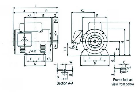
Fig.5
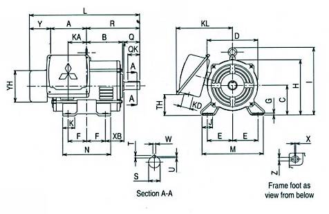
Fig.6
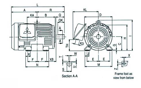
Fig.7
Dimensions(mm)
| Model | Frame No. | Output HP(kW) | Pole | Fig. | Motor | |||||||||||||||||||||||
|---|---|---|---|---|---|---|---|---|---|---|---|---|---|---|---|---|---|---|---|---|---|---|---|---|---|---|---|---|
| A | B | C* | D | E | F | G | H | I | J | K | KA | KD | KL | L | M | N | XB | TH | Y | YH | X | Z | ||||||
| SCL-KR | 90S | 1(0.75) | 4 | 5 | 132 | 103 | 90 | 165.7 | 70 | 50 | 3.2 | 173 | 220 | - | - | 68 | 27 | 157 | 278 | 175 | 125 | 56 | 81 | - | - | 10 | 10 | |
| 90L | 1.5(1.1) | 4 | 120 | 115 | 90 | 165.7 | 70 | 62.5 | 4 | 173 | 220 | - | - | 55 | 27 | 157 | 313 | 175 | 150 | 56 | 81 | - | - | 15 | 9 | |||
| 100L | 2(1-5) | 4 | 6 | 118 | 128 | 100 | 168 | 80 | 70 | 6.5 | 184 | - | 40 | 45 | 65 | 35 | 201 | 400 | 200 | 180 | 63 | 64 | 89 | 118 | 4 | 12 | ||
| 112M | 3(2.2) | 4 | 125 | 135 | 112 | 190 | 95 | 70 | 6.5 | 207 | 254 | 40 | 45 | 69 | 35 | 211 | 414 | 230 | 180 | 70 | 79 | 89 | 118 | 4 | 12 | |||
| 132S | 5(3.7) | 4 | 7 | 223 | 152 | 132 | 266 | 108 | 70 | 6.5 | 242 | 289 | 40 | 45 | 75 | 27 | 215 | 462 | 256 | 180 | 89 | 117 | - | - | 4 | 12 | ||
| 132M | 7.5(5.5) | 4 | 242 | 171 | 132 | 266 | 108 | 89 | 6.5 | 242 | 289 | 40 | 45 | 94 | 35 | 240 | 500 | 256 | 218 | 89 | 106 | - | - | 4 | 12 | |||
| 132ML | 10(7.5) | 4 | 270 | 171 | 132 | 266 | 108 | 89 | 6.5 | 242 | 289 | 40 | 45 | 122 | 35 | 240 | 528 | 256 | 218 | 89 | 106 | - | - | 4 | 12 | |||
* The perpendicular variation of tolerance for the shaft center is -0.5
| Model | Frame No. | Output HP(kW) | Pole | Fig. | Shaft End | Bering No. | Appoximate Weight (kg) | Appoximate Packing Dimensions (LxWxH) | Packing Weight (kg) | ||||||||||||||||||||
|---|---|---|---|---|---|---|---|---|---|---|---|---|---|---|---|---|---|---|---|---|---|---|---|---|---|---|---|---|---|
| Q | QK | R | S | T | U | W | Drive End | Opposite | |||||||||||||||||||||
| SCL-KR | 90S | 1(0.75) | 4 | 5 | 40 | 28 | 146 | 19 j6 | 6 | 3.5 | 6 | 6204ZZ | 6202ZZ | 15 | 368 x 280 x 250 | 16 | |||||||||||||
| 90L | 1.5(1.1) | 4 | 50 | 40 | 169 | 24 j6 | 7 | 4 | 8 | 6205ZZ | 6203ZZ | 18.6 | 390 x 280 x 250 | 18.2 | |||||||||||||||
| 100L | 2(1-5) | 4 | 6 | 60 | 45 | 193 | 28 j6 | 7 | 4 | 8 | 6206ZZ | 6205ZZ | 24.5 | 437 x 355 x 300 | 25.4 | ||||||||||||||
| 112M | 3(2.2) | 4 | 60 | 45 | 200 | 28 j6 | 7 | 4 | 8 | 6207ZZ | 6206ZZ | 32.8 | 504 x 411 x 327 | 39 | |||||||||||||||
| 132S | 5(3.7) | 4 | 7 | 80 | 63 | 239 | 38 k6 | 8 | 5 | 10 | 6308ZZ | 6207ZZ | 45.8 | 552 x 438 x 359 | 53 | ||||||||||||||
| 132M | 7.5(5.5) | 4 | 80 | 63 | 258 | 38 k6 | 8 | 5 | 10 | 6308ZZ | 6207ZZ | 60 | 602 x 475 x 369 | 68 | |||||||||||||||
| 132ML | 10(7.5) | 4 | 80 | 63 | 258 | 38 k6 | 8 | 5 | 10 | 6308ZZ | 6207ZZ | 68.2 | 630 x 475 x 369 | 76 | |||||||||||||||
SI-K REPULSION START TYPE
Totally Enclosed Type, IP 44 Degrees of Protection
SI-K 1HP 4P 100
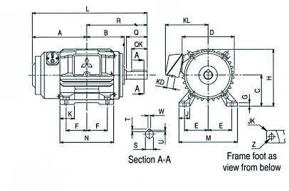
Fig.8
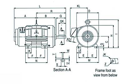
Fig.9
Dimensions(mm)
| Model | Frame No. | Output HP(kW) | Pole | Fig. | Motor | |||||||||||||||||
|---|---|---|---|---|---|---|---|---|---|---|---|---|---|---|---|---|---|---|---|---|---|---|
| A | B | C* | D | E | F | G | H | I | J | JK | K | KD | KL | L | M | N | Z | |||||
| SI-K | 100 | 1/2(0.4) | 4 | 8 | 170.5 | 128 | 100 | 208 | 80 | 70 | 12 | 204 | - | 40 | 3 | 40 | 27 | 161 | 343.5 | 200 | 175 | 12 |
| 100 | 1 (0.75) | 4 | 9 | 170.5 | 168.5 | 100 | 212 | 80 | 70 | 12 | 206 | 237.5 | 40 | 3 | 40 | 27 | 161 | 383.5 | 200 | 175 | 12 | |
| 100 | 1 3/4 (1.3) | 4 | 185.5 | 168.5 | 100 | 212 | 80 | 70 | 12 | 206 | 237.5 | 40 | 3 | 40 | 27 | 161 | 398.5 | 200 | 175 | 12 | ||
* The perpendicular variation of tolerance for the shaft center is -0.5
| Model | Frame No. |
Output HP(kW) |
Pole | Fig. | Shaft End | Bering No. | Appoximate Weight (kg) |
Appoximate Packing Dimensions (LxWxH) |
Packing Weight (kg) |
||||||||||||||||
|---|---|---|---|---|---|---|---|---|---|---|---|---|---|---|---|---|---|---|---|---|---|---|---|---|---|
| Q | QK | R | S | T | U | W | Drive End | Opposite | |||||||||||||||||
| SI-K | 100 | 1/2(0.4) | 4 | 8 | 40 | 28 | 173 | 16 j6 | 5 | 3 | 5 | 6205ZZ | 6203ZZ | 26.4 | 395 x 309 x 258 | 28.2 | |||||||||
| 100 | 1 (0.75) | 4 | 9 | 40 | 36 | 213 | 22 j6 | 7 | 4 | 8 | 6205ZZ | 6203ZZ | 32.0 | 424 x 309 x 258 | 34 | ||||||||||
| 100 | 1 3/4 (1.3) | 4 | 40 | 36 | 213 | 24 j6 | 7 | 4 | 8 | 6206ZZ | 6204ZZ | 36.6 | 522 x 372 x 320 | 43.6 | |||||||||||
Standard Specifications
| Item | Specifications | ||||||||||||||||||||||||||||||||
|---|---|---|---|---|---|---|---|---|---|---|---|---|---|---|---|---|---|---|---|---|---|---|---|---|---|---|---|---|---|---|---|---|---|
| Voltage and Frequency | 220-230V 50Hz, 220V 60Hz | ||||||||||||||||||||||||||||||||
| Starting Method, Enclosure Construction and Degrees of Protection |
|
||||||||||||||||||||||||||||||||
| Frame Material | SP-KR, SC-KR, SCL-KR : Steel Plate | ||||||||||||||||||||||||||||||||
| SI-K : Cast Iron | |||||||||||||||||||||||||||||||||
| Thermal Class | SP-KR, SC-KR, SI-K : Class E | ||||||||||||||||||||||||||||||||
| SCL-KR 90S-112M : Class B | |||||||||||||||||||||||||||||||||
| 132S ~ 132ML : Class F | |||||||||||||||||||||||||||||||||
| Circumstance Condition |
Ambient Temperature |
-20 ~ +40°C | |||||||||||||||||||||||||||||||
| Ambient Humidity |
85% RH or less (for Opened Protected & Drip-proof Structure) 95% RH or less (for Totally Enclosed Structure) |
||||||||||||||||||||||||||||||||
| Altitude | Less than 1,000m above sea level | ||||||||||||||||||||||||||||||||
| Environment | No bursting / erosive gas or vapor | ||||||||||||||||||||||||||||||||
| Coating | Colour | Munsell N5.5 (Gray) | |||||||||||||||||||||||||||||||
| Conformed Standard | IEC 60034-1 & JIS C 4203 (for SP-KR, SC-KR), JEC-2137-2000 (for SCL-KR, Sl-K) | ||||||||||||||||||||||||||||||||
Connection
