Contents Menu
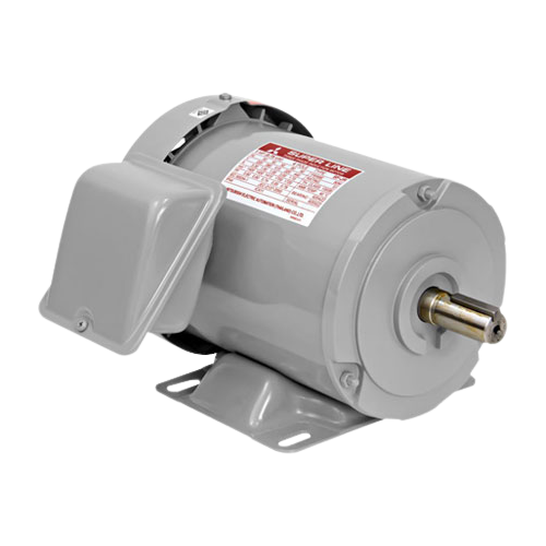
SUPER LINE J SERIES – THREE PHASE
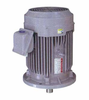
SUPER LINE J SERIES – THREE PHASE Mitsubishi Electric Three Phase Induction Motor is high performance and high reliability. It has been used in many leading industries where cost of production down time is critical.
Feature and Benefits
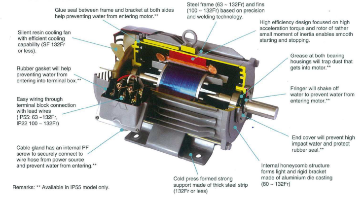
Compact Size and Light Weight
Size and weight reductions have been achieved by the use of steel-plate frame and aluminium brackets in the small capacity motors.
Highly Reliable Insulation Systems
Class B and F insulation systems are characterized by superior resistance to heat, humidity and chemicals for top-notch reliability.
Full Lineup
We have produced variety types of motors, ranged from 1/4 HP to 125 HP, thus providing a full lineup of motors ideal for any application.
Superlative Characteristics and High Reliability
Based on experience and technology accumulated over many years, along with an exacting quality-control system, each motor is ensured to exhibit only the finest characteristics.
Safety: All the rotating parts and the “live” areas are made sure that it cannot be accidentally touched directly.
Smooth Acceleration: The low moment of inertia of the rotor combined with the motor’s high acceleration torque, contributes to smooth starting and stopping.
Low Noise and Vibration Levels: This feature has been achieved due to our highly individualized electrical design, the ample rigidity and the precise machining of the motor frames and brackets, and the exact balancing of the rotor.
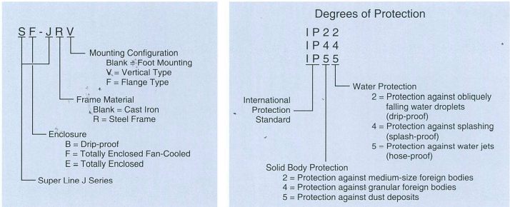
Significance of type designations and degrees of protection for three phase motor
Motor Section
Standard Specifications
| Item | Specifications | ||||||||||||||||||||||||||||||||||||||||||||||||||||||||||||||||||||||||||
|---|---|---|---|---|---|---|---|---|---|---|---|---|---|---|---|---|---|---|---|---|---|---|---|---|---|---|---|---|---|---|---|---|---|---|---|---|---|---|---|---|---|---|---|---|---|---|---|---|---|---|---|---|---|---|---|---|---|---|---|---|---|---|---|---|---|---|---|---|---|---|---|---|---|---|---|
| Voltage and Frequency | LT: 10HP and below = 220/380~415V 50Hz, 220/440V 60Hz HT: 5HP and above = 380~415V 50Hz, 380~440V 60Hz (Suitable for Υ - ∆ starting) |
||||||||||||||||||||||||||||||||||||||||||||||||||||||||||||||||||||||||||
| Enclosure Construction and Degrees of Protection |
|
||||||||||||||||||||||||||||||||||||||||||||||||||||||||||||||||||||||||||
| Frame material | 63M ~ 132M : Steel Plate |
||||||||||||||||||||||||||||||||||||||||||||||||||||||||||||||||||||||||||
| Power transmission system | Direct-coupled and belt driven, for up to 10HP 2-pole motor and all model 4-pole & 6-pole motor. Direct-coupled, for 2-pole motor with 15HP and above. |
||||||||||||||||||||||||||||||||||||||||||||||||||||||||||||||||||||||||||
| Direction of Rotation | Counter-Clockwise (CCW) viewed from shaft-enf side. | ||||||||||||||||||||||||||||||||||||||||||||||||||||||||||||||||||||||||||
| Thermal Class | IP22 and IP44 : 90L and below Class B 100L and above Class F IP55 : All Models Class F |
||||||||||||||||||||||||||||||||||||||||||||||||||||||||||||||||||||||||||
| Cirumstance Condition | Ambient Temperature | -20 ~ +40˚C | |||||||||||||||||||||||||||||||||||||||||||||||||||||||||||||||||||||||||
| Ambient Humidity | 85% RH.or (for Drip-proof Structure) 95% RH or less (for Totally Enclosed Structure) |
||||||||||||||||||||||||||||||||||||||||||||||||||||||||||||||||||||||||||
| Altitude | Less than 1,000m above sea level | ||||||||||||||||||||||||||||||||||||||||||||||||||||||||||||||||||||||||||
| Environment | No bursting / erosive gas or vapor | ||||||||||||||||||||||||||||||||||||||||||||||||||||||||||||||||||||||||||
| Connection Type |
|
||||||||||||||||||||||||||||||||||||||||||||||||||||||||||||||||||||||||||
| Coating Colour | Munsell N5.5 (Gray) | ||||||||||||||||||||||||||||||||||||||||||||||||||||||||||||||||||||||||||
| Conformed Standard | IEC 60034-1 & JIS C 4210 (for Horizontal Type), JEC-2137-2000 (for Vertical Type) | ||||||||||||||||||||||||||||||||||||||||||||||||||||||||||||||||||||||||||
Three Phase Motor Characteristics
LT (220/ 380~415V 50Hz, 220/ 440V 60Hz)
SF-JR IP44 63M~90L 4P (Thermal Class B)
SF-JR(V) IP55 63M~132M (Thermal Class F)
| Pole | Output | Frame No. | Full Load Current(A) I Full Load Revolution(r/min) | |||||
|---|---|---|---|---|---|---|---|---|
| HP | kW | 220V 50Hz | 380V 50Hz | 415V 50 Hz | 220V 60Hz | 440V 60Hz | ||
| 2 | 1/4 | 0.2 | 63M | 0.97/2810 | 0.56/2810 | 0.58 / 2840 | 0.94/3360 | 0.53 / 3380 |
| 1/2 | 0.4 | 71M | 1.73/2830 | 1.0 / 2830 | 1.0/2860 | 1.65 / 3420 | 0.9 / 3440 | |
| 1 | 0.75 | SOM | 3.1/2830 | 1.8/2830 | 1.8 / 2860 | 2.9 / 3400 | 1.6/3430 | |
| 2 | 1.5 | 90L | 5.6/ 2860 | 3.2/2860 | 3.1 /2870 | 5.2/3440 | 2.8 / 3450 | |
| 3 | 2.2 | 90L | 7.8/2850 | 4.5/2850 | 4.3/2870 | 7.6/3430 | 4.0 / 3460 | |
| 5 | 3.7 | 112M | 12.8/2890 | 7.4 / 2890 | 7.2/2910 | 12.6/3470 | 6.5/3493 | |
| 7.5 | 5.5 | 132S | 20.1/2900 | 11.6/2900 | 11.6/2910 | 18.9/3480 | 10/3500 | |
| 10 | 7.5 | 132S | 25/2910 | 14.5/2910 | 14.1/2920 | 24.5 / 3490 | 12.4/3510 | |
| 4 | 1/4 | 0.2 | 63M | 1.11/1430 | 0.64/1430 | 0.69/1440 | 0.97/1730 | 0.61 /1750 |
| 1/2 | 0.4 | 71M | 2.0/1410 | 1.15/1410 | 1.2/1430 | 1.8/1700 | 1.0/1730 | |
| 1 | 0.75 | 80M | 3.3/1400 | 1.9/1400 | 1.95/1410 | 3.0/1700 | 1.7/1720 | |
| 2 | 1.5 | 90L | 5.9/1430 | 3.4/1430 | 3.4/1440 | 5.5/1710 | 3.1 /1730 | |
| 3 | 2.2 | 100L | 8.7/1420 | 5.0/1420 | 4.9/1430 | 8.5/1710 | 4.6/1730 | |
| 5 | 5.7 | 112M | 13.7/1420 | 7.9/1420 | 7.7/1430 | 13.5/1710 | 7.2/1730 | |
| 7.5 | 5.5 | 132S | 20.4/1430 | 11.8/1430 | 11.1/1440 | 19.9/1720 | 10.3/1740 | |
| 10 | 7.5 | 132M | 27/1430 | 15.4/1430 | 14.6/1440 | 26/1720 | 13.5/1740 | |
| 6 | 1/4 | 0.2 | 71M | 1.21/920 | 0.7/920 | 0.7/930 | 1.12/1100 | 0.65/1120 |
| 1/2 | 0.4 | 80M | 2.25/920 | 1.3/920 | 1.3/930 | 2.1/1100 | 1.2/1110 | |
| 1 | 0.75 | 901 | 3.6/940 | 2.1/940 | 2.2/950 | 3.5/1130 | 2.0/1150 | |
| 2 | 1.5 | 100L | 7.0/930 | 4.0/930 | 4.0/940 | 6.6/1110 | 3.6/1120 | |
| 3 | 2.2 | 112M | 9.5/940 | 5.5/940 | 5.4/950 | 9.0/1120 | 5.1/1140 | |
| 5 | 3.7 | 132S | 15.2/940 | 8.8/940 | 8.4/950 | 14.2/1130 | 7.8/1150 | |
| 7.5 | 5.5 | 132M | 22 / 950 | 12.8/950 | 13/960 | 21/1140 | 11.5/1150 | |
SB-JR(V) IP22 80M~90L(Thermal Class B), 100L~132M (Thermal Class F)
| Pole | Output | Frame No. | Full Load Current(A) I Full Load Revolution(r/min) | |||||
|---|---|---|---|---|---|---|---|---|
| HP | kW | 220V 50Hz | 380V 50Hz | 415V 50 Hz | 220V 60Hz | 440V 60Hz | ||
| 4 | 1 | 0.75 | 80M | 3.5/1400 | 2.0/1400 | 2.3/1410 | 2.9/1700 | 1.7/1720 |
| 2 | 1.5 | 90L | 6.2/1450 | 3.6/1450 | 4.0/1460 | 5.5/1720 | 3.2/1740 | |
| 3 | 2.2 | 100L | 8.7/1420 | 5.0/1420 | 4.9/1430 | 8.5/1710 | 4.6/1730 | |
| 5 | 3.7 | 112M | 13.7/1420 | 7.9/1420 | 7.7/1430 | 13.5/1710 | 7.2/1730 | |
| 7.5 | 5.5 | 132S | 20.4/1430 | 11.8/1430 | 11.8/1440 | 19.4/1720 | 11.2/1730 | |
| 10 | 7.5 | 132M | 26.4/1440 | 15.2/1440 | 15.5/1450 | 25.4/1730 | 13.7/1740 | |
Three Phase Motor Characteristics
HT (380~415V 50Hz, 380~440V 60Hz)
SF-JR(V) IP55 112M~132M (Thermal Class F), SF-J(V) 160M~250M (Thermal Class F)
| Pole | Output | Frame No. | Full Load Current(A) I Full Load Revolution(r/min) | ||||
|---|---|---|---|---|---|---|---|
| HP | kW | 380V 50Hz | 415V 50 Hz | 380V 60Hz | 440V 60Hz | ||
| 2 | 5 | 3.7 | 112M | 7.5/2890 | 7.3/2910 | 7.3/3470 | 6.6/3490 |
| 7.5 | 5.5 | 132S | 11.6/2900 | 11.6/2910 | 10.9/3480 | 10/3500 | |
| 10 | 7.5 | 132S | 14.4/2900 | 14.0/2920 | 14.2/3480 | 12.4/3510 | |
| 15 | 11 | 160M | 21.5/2910 | 20.5/2920 | 21/3490 | 18.5/3510 | |
| 20 | 15 | 160M | 28/2910 | 27/2920 | 27/3490 | 24/3510 | |
| 25 | 18.5 | 160L | 34/2910 | 33/2930 | 33/3490 | 29/3510 | |
| 30 | 22 | 180M | 42/2910 | 39/2930 | 41/3490 | 36/3510 | |
| 40 | 30 | 180L | 55/2920 | 52/2940 | 54/3490 | 47/3520 | |
| 50 | 37 | 200L | 69/2920 | 67/2940 | 67/3510 | 60/3530 | |
| 60 | 45 | 200L | 83/2920 | 80.5/2940 | 81/3510 | 72/3530 | |
| 75 | 55 | 225S | 103/2930 | 101/2940 | 101/3520 | 89/3540 | |
| 4 | 5 | 3.7 | 112M | 7.9/1420 | 7.7/1430 | 7.8/1710 | 7.2/1730 |
| 7.5 | 5.5 | 132S | 11.8/1430 | 11.1/1440 | 11.5/1720 | 103.1740 | |
| 10 | 7.5 | 132M | 15.5/1430 | 14.5/1440 | 15.0/1720 | 13.4/1740 | |
| 15 | 11 | 160M | 22.5/1430 | 21.5/1440 | 21.5/1720 | 19/1740 | |
| 20 | 15 | 160L | 30/1450 | 31/1460 | 28.5/1740 | 26/1760 | |
| 25 | 18.5 | 180M | 43/1460 | 42/1470 | 42/1750 | 32/1760 | |
| 30 | 22 | 180M | 43/1460 | 42/1470 | 42/1750 | 38/1760 | |
| 40 | 30 | 180L | 58/1460 | 56/1470 | 56/1750 | 49/1760 | |
| 50 | 37 | 200L | 69/1450 | 65/1460 | 69/1750 | 60/1770 | |
| 60 | 45 | 200L | 83.5/1450 | 82/1460 | 82/1750 | 72/1770 | |
| 75 | 55 | 225S | 104/1460 | 102/1470 | 101/1760 | 90/1770 | |
| 100 | 75 | 250S | 139/1470 | 137/1470 | 135/1760 | 120/1770 | |
| 125 | 93 | 250M | 173/1470 | 172/1470 | 167/1760 | 148/1770 | |
| 6 | 5 | 3.7 | 132S | 8.9/940 | 8.5/950 | 8.3/1130 | 7.9/1150 |
| 7.5 | 5.5 | 132M | 12.8/950 | 13/960 | 12.1/1140 | 11.5/1150 | |
| 10 | 7.5 | 160M | 16.5/950 | 16.5/960 | 16/1130 | 14.5/1150 | |
| 15 | 11 | 160L | 24/960 | 24/970 | 23/1140 | 21/1160 | |
| 20 | 15 | 180M | 32/960 | 32/970 | 31/1150 | 28/1170 | |
| 25 | 18.5 | 180L | 39/960 | 37/970 | 38/1150 | 33/1170 | |
| 30 | 22 | 180L | 45/960 | 43/970 | 44/1150 | 39/1170 | |
| 40 | 30 | 200L | 60/960 | 59/970 | 58/1150 | 51/1170 | |
| 50 | 37 | 200L | 74/960 | 74/975 | 72/1150 | 64/1170 | |
| 60 | 45 | 225S | 89/960 | 90/975 | 86/1150 | 79/1170 | |
SB-JR(V) IP22 112M 132M (Thermal Class F)
| Pole | Output | Frame No. | Full Load Current(A) I Full Load Revolution(r/min) | ||||
|---|---|---|---|---|---|---|---|
| HP | kW | 380V 50Hz | 415V 50 Hz | 380V 60Hz | 440V 60Hz | ||
| 4 | 5 | 3.7 | 112M | 7.9/1420 | 7.7/1430 | 7.8/1710 | 7.2/1730 |
| 7.5 | 5.5 | 132S | 11.8/1430 | 11.8/1440 | 11.2/1720 | 10.6/1730 | |
| 10 | 7.5 | 132M | 15.4/1440 | 15.5/1450 | 14.7/1730 | 13.6/1750 | |
SB-JR 80M~132M HORIZONTAL TYPE
Drip-Proof Type, IP 22 Degrees of Protection
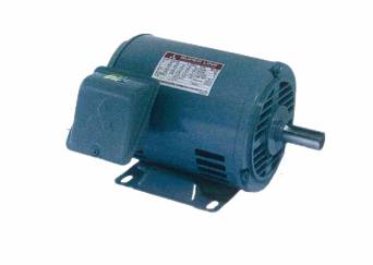
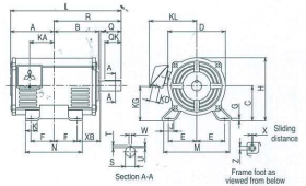
Fig.2
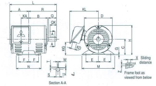
Fig.1
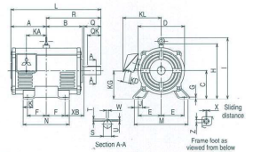
Fig.3
Dimensions(mm)
| Model | Frame No. | Output HP (kW) | Fig. | Motor | Terminal Box | ||||||||||||||||||||||
|---|---|---|---|---|---|---|---|---|---|---|---|---|---|---|---|---|---|---|---|---|---|---|---|---|---|---|---|
| 2-Pole | 4-Pole | 6-Pole | A | B | C* | D | E | F G | H | I | J | K | L | M | ML | N | X | XB | Z | KA | KG | KD | KL | ||||
| SB-JR | 80M | 1(0.75) | 1(0.75) | 1/2(0.4) | 1 | 95 | 95 | 80 | 141 | 62.5 | 50 | 3.2 | 150.5 | - | - | - | 235 | 160 | - | 125 | 15 | 50 | 9 | 39.5 | 63 | 27 | 144 |
| 90L | 2(1.5), 3(2.2) | 2(1-5) | 1(0.75) | 112.5 | 112.5 | 90 | 168 | 70 | 62.5 | 4 | 174 | - | - | - | 281 | 175 | - | 150 | 15 | 56 | 9 | 53 | 76 | 27 | 157 | ||
| 100L | - | 3(2.2) | 2(1.5) | 2 | 130 | 128 | 100 | 168 | 80 | 70 | 6.5 | 184 | - | 40 | 45 | 323 | 200 | 212 | 180 | 4 | 63 | 12 | 65 | 86 | 27 | 157 | |
| 112M | 5(3.7) | 5(3.7) | 3(2.2) | 3 | 136 | 135 | 112 | 190 | 95 | 70 | 6.5 | 220 | 254 | 40 | 45 | 336 | 230 | 242 | 180 | 4 | 70 | 12 | 69 | 101 | 27 | 168 | |
| 132S | 7.5(5.5), 10(7.5) | 7.5(5.5) | 5(3.7) | 153 | 152 | 132 | 220 | 108 | 70 | 6.5 | 255 | 289 | 40 | 45 | 392 | 256 | 268 | 180 | 4 | 89 | 12 | 75 | 118 | 27 | 185 | ||
| 132M | - | 10(7.5) | 7.5(5.5) | 172 | 171 | 132 | 220 | 108 | 89 | 6.5 | 255 | 289 | 40 | 45 | 430 | 256 | 268 | 218 | 4 | 89 | 12 | 94 | 118 | 27 | 185 | ||
* The perpendicular variation of tolerance for the shaft center is -0.5
| Model | Frame No. | Shaft End | Bearing No. | Approximate Weight (kg) | Approximate Packing Dimensions (LxWxH) | Packing Weight (kg) | |||||||||||||||||||||||
|---|---|---|---|---|---|---|---|---|---|---|---|---|---|---|---|---|---|---|---|---|---|---|---|---|---|---|---|---|---|
| Q | QK | R | S | T | U | W | Drive End | Opposite | 2-Pole | 4-Pole | 6-Pole | 2-Pole | 4-Pole | 6-Pole | |||||||||||||||
| SB-JR | 80M | 40 | 32 | 140 | 19j6 | 6 | 3.5 | 6 | 6204ZZ | 6203ZZ | 9 | 11 | 11 | 295 x 270 x 206 | 10 | 10.8 | 12 | ||||||||||||
| 90L | 50 | 40 | 168.5 | 24 j6 | 7 | 4 | 8 | 6205ZZ | 6204ZZ | 16,16 | 16 | 16 | 350x280x350 | 17,16 | 17 | 17 | |||||||||||||
| 100L | 60 | 45 | 193 | 28 j6 | 7 | 4 | 8 | 6206ZZ | 6205ZZ | - | 22 | 24 | 409 x 355 x 300 | - | 21.2 | 27 | |||||||||||||
| 112M | 60 | 45 | 200 | 28 j6 | 7 | 4 | 8 | 6207ZZ | 6206ZZ | 27 | 30 | 31 | 477x399x315 | 31 | 34 | 35 | |||||||||||||
| 132S | 80 | 63 | 239 | 38k6 | 8 | 5 | 10 | 6308ZZ | 6207ZZ | 38,42 | 40 | 41 | 526x403x347 | 42, 46 | 44 | 45 | |||||||||||||
| 132M | 80 | 63 | 258 | 38k6 | 8 | 5 | 10 | 6308ZZ | 6207ZZ | - | 51 | 52 | 526 x 403 x 347 | - | 55 | 56 | |||||||||||||
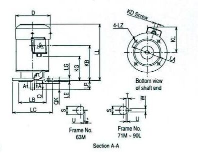
SB-JRV 80M~132M VERTICAL TYPE
Drip-Proof Type,
IP 22 Degrees of Protection
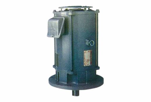
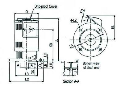
Fig.4
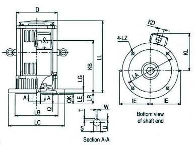
Fig.5
Dimensions(mm)
| Model | Flange No. | Frame No. | Output HP (kW) | Fig. | Motor | Terminal Box | ||||||||||||
|---|---|---|---|---|---|---|---|---|---|---|---|---|---|---|---|---|---|---|
| 2-Pole | 4-Pole | 6-Pole | D | IE | LA | LB | LC | LE | LG | LL* | LZ | KB | KD | KL | ||||
| SB-JRV | FF165 | 80M | 1(0.75) | 1(0.75) | 1/2(0.4) | 4 | 141 | - | 165 | 130 j6 | 200 | 3.5 | 12 | 234(227) | 12 | 171.5 | 27 | 145 |
| FF165 | 90L | 2(1.5), 3(2.2) | 2(1-5) | 1(0.75) | 168 | - | 165 | 130 j6 | 200 | 3.5 | 12 | 270(261) | 12 | 201.5 | 27 | 158 | ||
| FF215 | 100L | - | 3(2.2) | 2(1-5) | 5 | 168 | - | 215 | 180 j6 | 250 | 4 | 16 | 320(300) | 14.5 | 237 | 27 | 155 | |
| FF215 | 112M | 5(3.7) | 5(3.7) | 3(2.2) | 190 | 141.5 | 215 | 180 j6 | 250 | 4 | 16 | 352(329) | 14.5 | 263 | 27 | 166 | ||
| FF265 | 132S | 7.5(5.5), 10(7.5) | 7.5(5.5) | 5(3.7) | 220 | 156.5 | 265 | 230 j6 | 300 | 4 | 20 | 393(369) | 14.5 | 292 | 27 | 181 | ||
| FF265 | 132M | - | 10(7.5) | 7.5(55) | 220 | 156.5 | 265 | 230 j6 | 300 | 4 | 20 | 431(407) | 14.5 | 330 | 27 | 181 | ||
* ( ) is dimension of vertical type without drip-proof cover.
| Model | Flange No. | Frame No. | Shaft End | Bearing No. | Approximate Weight (kg) | Approximate Packing Dimensions (LxWxH) | Packing Weight (kg) | |||||||||||||||
|---|---|---|---|---|---|---|---|---|---|---|---|---|---|---|---|---|---|---|---|---|---|---|
| LR | Q | QK | S | T | U | W | Drive End | Opposite | 2-Pole | 4-Pole | 6-Pole | 2-Pole | 4-Pole | 6-Pole | ||||||||
| SB-JRV | FF165 | 80M | 40 | 40 | 32 | 19 j6 | 6 | 3.5 | 6 | 6204ZZ | 6203ZZ | 12 | 14 | 14 | 305 x 260 x 235 | 14 | 16 | 16 | ||||
| FF165 | 90L | 50 | 50 | 40 | 24 j6 | 7 | 4 | 8 | 6205ZZ | 6204ZZ | 19,19 | 19 | 19 | 370 x 280 x 235 | 21,21 | 21 | 21 | |||||
| FF215 | 100L | 60 | 60 | 45 | 28 j6 | 7 | 4 | 8 | 6206ZZ | 6205ZZ | - | 28 | 30 | 430 x 340 x 330 | - | 30 | 32 | |||||
| FF215 | 112M | 60 | 60 | 45 | 28 j6 | 7 | 4 | 8 | 6207ZZ | 6206ZZ | 37 | 40 | 41 | 390x387x354 | 41 | 44 | 45 | |||||
| FF265 | 132S | 80 | 80 | 63 | 38 k6 | 8 | 5 | 10 | 6308ZZ | 6207ZZ | 52, 56 | 54 | 55 | 569x427x384 | 59, 63 | 61 | 62 | |||||
| FF265 | 132M | 80 | 80 | 63 | 38 k6 | 8 | 5 | 10 | 6308ZZ | 6207ZZ | - | 67 | 68 | 607 x 427 x 384 | - | 74 | 75 | |||||
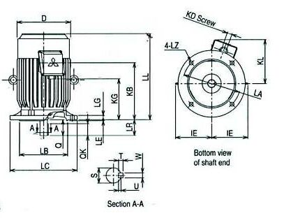
SF-JR 63M~90L HORIZONTAL TYPE
Totally-Enclosed Fan-Cooled Type, IP 44 Degrees of Protection
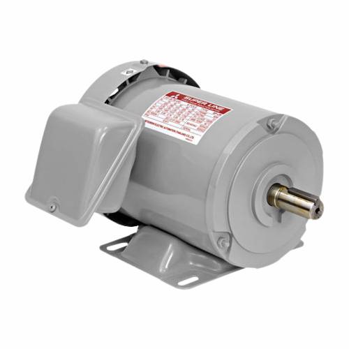
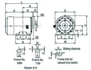
Fig.6
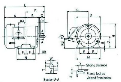
Fig.7
| Model | Frame No. | Shaft End | Bearing No. | Approximate Weight (kg) | Approximate Packing Dimensions (LxWxH) | Packing Weight (kg) | ||||||||||||||
|---|---|---|---|---|---|---|---|---|---|---|---|---|---|---|---|---|---|---|---|---|
| Q | QK | R | S | T | U | W | Drive End | Opposite | ||||||||||||
| SF-JR | 63M | 23 | - | 103 | 11 h6 | - | 1 | - | 6201ZZ | 6201ZZ | 5.6 | 245x 165x170 | 6 | |||||||
| 71M | 30 | 25 | 120 | 14 j6 | 5 | 3 | 5 | 6202ZZ | 6201ZZ | 8.2 | 270 x 200x 185 | 7.5 | ||||||||
| 80M | 40 | 32 | 140 | 19 j6 | 6 | 3.5 | 6 | 6204ZZ | 6203ZZ | 11 | 315x270x206 | 11.7 | ||||||||
| 90L | 50 | 40 | 168.5 | 24 j6 | 7 | 4 | 8 | 6205ZZ | 6204ZZ | 20 | 368 x 280 x 226 | 20 | ||||||||
Dimensions(mm)
| Model | Frame No. | Output HP (kW) | Pole | Fig. | Motor | Terminal Box | ||||||||||||||||
|---|---|---|---|---|---|---|---|---|---|---|---|---|---|---|---|---|---|---|---|---|---|---|
| A | B | C* | D | E | F | G | H | L | M | N | X | XB | Z | KA | KG | KD | KL | |||||
| SF-JR | 63M | 1/4(0.2) | 4 | 6 | 113 | 77 | 63 | 127 | 50 | 40 | 2.3 | 127 | 216 | 135 | 100 | 12 | 40 | 7 | - | - | - | - |
| 71M | 1/2(0.4) | 118 | 87 | 71 | 148 | 56 | 45 | 3.2 | 145 | 238 | 148 | 110 | 18 | 45 | 7 | - | - | - | - | |||
| 80M | 1(0.75) | 7 | 122 | 95 | 80 | 166 | 62.5 | 50 | 3.2 | 166 | 262 | 160 | 125 | 15 | 50 | 9 | 39.5 | 63 | 27 | 145 | ||
| 90L | 2(1.5) | 143 | 114 | 90 | 188 | 70 | 62.5 | 4 | 187 | 311.5 | 175 | 150 | 15 | 56 | 9 | 53 | 76 | 27 | 158 | |||
* The perpendicular variation of tolerance for the shaft center is -0.5
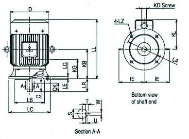
SF-JR 63M~132M HORIZONTAL TYPE
Totally Enclosed Fan Cooled Type, IP 55 Degrees of Protection
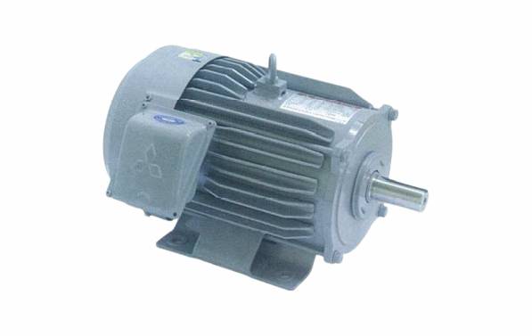
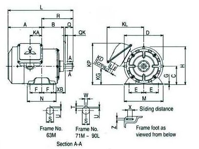
Fig.8
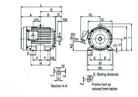
Fig.9
Dimensions(mm)
| Model | Frame No. | Output HP (kW) | Fig. | Motor | Terminal Box | |||||||||||||||||||||||
|---|---|---|---|---|---|---|---|---|---|---|---|---|---|---|---|---|---|---|---|---|---|---|---|---|---|---|---|---|
| 2-Pole | 4-Pole | 6-Pole | A | B | C* | D | E | F | G | H | I | J | K | L | M | ML | N | X | XB | Z | KA | KG | KD | KL | KP** | |||
| SF-JR | 63M | 1/4(0.2) | 1/4(0.2) | - | 8 | 121.4 | 73.6 | 63 | 130 | 50 | 40 | 2.3 | 126.3 | - | - | - | 224.4 | 135 | - | 100 | 12 | 40 | 7 | 38.4 | 75 | PF1/2 | 130 | 162 |
| 71M | 1/2(0.4) | 1/2(0.4) | 1/4(0.2) | 128.5 | 83 | 71 | 147.6 | 56 | 45 | 3.2 | 144.8 | - | - | - | 248.5 | 148 | - | 110 | 18 | 45 | 7 | 44.5 | 67 | PF1/2 | 140 | 161 | ||
| 80M | 1(0.75) | 1(0.75) | 1/2(0.4) | 122 | 98 | 80 | 161.6 | 62.5 | 50 | 3.2 | 165.4 | - | - | - | 262 | 160 | - | 125 | 15 | 50 | 9 | 39.5 | 38 | PF374 | 145 | - | ||
| 90L | 2(1.5), 3(2.2) | 2(1.5) | 1(0.75) | 143 | 117 | 90 | 183.6 | 70 | 62.5 | 4 | 186.3 | - | - | - | 311.5 | 175 | - | 150 | 15 | 56 | 9 | 53 | 59 | PF3/4 | 158 | - | ||
| 100L | - | 3(2.2) | 2(1.5) | 9 | 173 | 131 | 100 | 207 | 80 | 70 | 6.5 | 203.5 | 230 | 40 | 45 | 366 | 200 | 212 | 180 | 4 | 63 | 12 | 65 | 64 | PF3/4 | 170 | - | |
| 112M | 5(3.7) | 5(3.7) | 3(2.2) | 181 | 138 | 112 | 228 | 95 | 70 | 6.5 | 226 | 253 | 40 | 45 | 381 | 230 | 242 | 180 | 4 | 70 | 12 | 69 | 87 | PF3/4 | 182 | - | ||
| 132S | 7.5(5.5), 10(7.5) | 7.5(5.5) | 5(3.7) | 211.5 | 155 | 132 | 266 | 108 | 70 | 6.5 | 265 | 288 | 40 | 45 | 450.5 | 256 | 268 | 180 | 4 | 89 | 12 | 75 | 96 | PF1 | 210 | - | ||
| 132M | - | 10(7.5) | 7.5(5.5) | 230.5 | 174 | 132 | 266 | 108 | 89 | 6.5 | 265 | 288 | 40 | 45 | 488.5 | 256 | 268 | 218 | 4 | 89 | 12 | 94 | 96 | PF1 | 210 | - | ||
* The perpendicular variation of tolerance for the shaft center is -0.5
* ** This dimension is for model which KP > H only.
| Model | Frame No. | Shaft End | Bearing No. | Approximate Weight (kg) | Approximate Packing Dimensions (LxWxH) | Packing Weight (kg) | |||||||||||||||||||
|---|---|---|---|---|---|---|---|---|---|---|---|---|---|---|---|---|---|---|---|---|---|---|---|---|---|
| Q | QK | R | S | T | U | W | Drive End | Opposite | 2-Pole | 4-Pole | 6-Pole | 2-Pole | 4-Pole | 6-Pole | |||||||||||
| SF-JR | 63M | 23 | - | 103 | 11 h6 | - | 1 | - | 6201ZZ | 6201ZZ | 6.5 | 6.6 | - | 245x221 x 193 | 5.7 | 6 | - | ||||||||
| 71M | 30 | 25 | 120 | 14 j6 | 5 | 3 | 5 | 6202ZZ | 6201ZZ | 8.0 | 9.2 | 9.0 | 275x256x 180 | 7.2 | 8 | 8 | |||||||||
| 80M | 40 | 32 | 140 | 19 j6 | 6 | 3.5 | 6 | 6204ZZ | 6203ZZ | 10.5 | 11 | 11 | 315x270x206 | 10.7 | 11.7 | 11.5 | |||||||||
| 90L | 50 | 40 | 168.5 | 24 j6 | 7 | 4 | 8 | 6205ZZ | 6204ZZ | 17,20.5 | 20 | 21.5 | 368x280x226 | 17.2,21 | 20 | 19.5 | |||||||||
| 100L | 60 | 45 | 193 | 28 j6 | 7 | 4 | 8 | 6206ZZ | 6205ZZ | - | 24 | 25 | 430 x 355 x 300 | - | 28 | 27 | |||||||||
| 112M | 60 | 45 | 200 | 28 j6 | 7 | 4 | 8 | 6207ZZ | 6206ZZ | 33 | 36 | 37 | 477x399x315 | 40 | 42 | 44 | |||||||||
| 132S | 80 | 63 | 239 | 38 k6 | 8 | 5 | 10 | 6308ZZ | 6207ZZ | 47, 55 | 48 | 50 | 579 x 435 x 347 | 55, 63 | 56 | 58 | |||||||||
| 132M | 80 | 63 | 258 | 38 k6 | 8 | 5 | 10 | 6308ZZ | 6207ZZ | - | 58 | 61 | 579 x 435 x 347 | - | 66 | 69 | |||||||||
SF-J 160M~250M HORIZONTAL TYPE
Totally Enclosed Fan Cooled Type, IP 55 Degrees of Protection
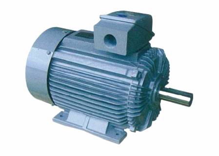
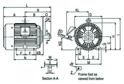
Fig.10
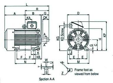
Fig.11
Dimensions(mm)
| Model | Frame No. | Output HP (kW) | Fig. | Motor | Terminal Box | ||||||||||||||||||||||
|---|---|---|---|---|---|---|---|---|---|---|---|---|---|---|---|---|---|---|---|---|---|---|---|---|---|---|---|
| 2-Pole | 4-Pole | 6-Pole | A | B | C* | D | E | F | G | H | I | J | JK | K | L | M | N | XB | Z | KA | KG | KD | KL | KP | |||
| SF-J | 160M | 15(11), 20(15) | 15(11) | 10(7.5) | 10 | 252 | 207 | 160 | 324 | 127 | 105 | 20 | 322 | 373 | 55 | R6 | - | 575 | 310 | 260 | 108 | 15 | - | 127 | PF 1 1/4 | 271 | - |
| 160L | 25(18.5) | 20(15) | 15(11) | 274 | 229 | 160 | 324 | 127 | 127 | 20 | 322 | 373 | 55 | R6 | - | 619 | 310 | 304 | 108 | 15 | - | 127 | PF1 1/4 | 271 | - | ||
| 180M | 30(22) | 25(18.5), 30(22) | 20(15) | 294.5 | 239 | 180 | 376 | 139.5 | 120.5 | 22 | 367 | 427 | 70 | R6 | - | 646 | 350 | 300 | 121 | 15 | - | 151 | PF1 1/2 | 295 | - | ||
| 180L | 40(30) | 40(30) | 25(18.5), 30(22) | 313.5 | 258 | 180 | 376 | 139.5 | 139.5 | 22 | 367 | 427 | 70 | R6 | - | 684 | 350 | 338 | 121 | 15 | - | 151 | PF1 1/2 | 295 | - | ||
| 200L | 50(37), 60(45) | 50(37), 60(45) | 40(30), 50(37) | 11 | 370.5 | 281 | 200 | 410 | 159 | 152.5 | 25 | 405 | - | 80 | R6 | 78 | (766) 796 | 390 | 369 | 133 | 18.5 | 120 | 476 | PF2 | - | 550 | |
| 225S | 75(55) | 75(55) | 60(45) | 380 | 287.5 | 225 | 459 | 178 | 143 | 28 | 457 | - | 80 | R8 | 82 | (782) 812 | 430 | 350 | 149 | 18.5 | 120 | 528 | PF2 | - | 602 | ||
| 250S | - | 100(75) | - | 417.5 | 318.7 | 250 | 495 | 203 | 155.5 | 30 | - | - | 80 | R8 | 95 | 881 | 486 | 387 | 168 | 24 | 136.5 | 560 | PF2 1/2 | - | 643 | ||
| 250M | - | 125(93) | - | 436.5 | 337.7 | 250 | 495 | 203 | 174.5 | 30 | - | - | 80 | R8 | 95 | 919 | 486 | 425 | 168 | 24 | 155.5 | 560 | PF2 1/2 | - | 643 | ||
* The perpendicular variation of tolerance for the shaft center is -0.5
| Model | Frame No. | Shaft End | Bearing No. | Approximate Weight (kg) | Approximate Packing Dimensions (LxWxH) | Packing Weight (kg) | ||||||||||||||||||
|---|---|---|---|---|---|---|---|---|---|---|---|---|---|---|---|---|---|---|---|---|---|---|---|---|
| Q | QK | R | S | T | U | w | Drive End | Opposite | 2-Pole | 4-Pole | 6-Pole | 2-Pole | 4-Pole | 6-Pole | ||||||||||
| SF-J | 160M | 110 | 90 | 323 | 42 k6 | 8 | 5 | 12 | 6309ZZ | 6308ZZ | 105,115 | 107 | 107 . | 743 x 601 x 494 | 126,136 | 128 | 128 | |||||||
| 160L | 110 | 90 | 345 | 42 k6 | 8 | 5 | 12 | 6309ZZ | 6308ZZ | 145 | 135 | 135 | 787 x 601 x 494 | 166 | 156 | 156 | ||||||||
| 180M | 110 | 90 | 351.5 | 48 k6 | 9 | 5.5 | 14 | 6311ZZ | 6310ZZ | 190 | 185,195 | 195 | 814x651 x 548 | 214 | 209, 219 | 219 | ||||||||
| 180L | 110 | 90 | 370.5 | 55 m6 | 10 | 6 | 16 | 6312ZZ | 6310ZZ | 220 | 230 | 220,235 | 852 x 651 x 548 | 244 | 254 | 244,259 | ||||||||
| 200L | (110) 140 |
(90) 110 |
(395.5) 425.5 |
(55 m 6) 60 m6 |
(10) 11 |
(6) 7 |
(16) 18 |
(6312ZZC3) 6313ZZ | (6311ZZC3) 6311ZZ | 280,195 | 285,310 | 295, 340 | 964 x 542 x 691 | 307, 222 | 312,337 | 322, 367 | ||||||||
| 225S | (110) 140 |
(90) 110 |
(402) 432 |
(55 m6) 65 m6 |
(10) 11 |
(6) 7 |
(16) 18 |
(6312ZZC3) 6315ZZ | (6312ZZC3) 6312ZZ | 315 | 345 | 370 | 980 x 591 x 774 | 345 | 375 | 400 | ||||||||
| 250S | 140 | 110 | 463.5 | 75 rn6 | 12 | 7.5 | 20 | 6318ZZ | 6315ZZ | - | 490 | - | 1087x627x824 | - | 505 | - | ||||||||
| 250M | 140 | 110 | 482.5 | 75 m6 | 12 | 7.5 | 20 | 6318ZZ | 6315ZZ | - | 557 | - | 1087 x 627 x 824 | - | 572 | - | ||||||||
() is dimension for 2-pole motors.
SF-JRV 63M~132M & SF-JV 160M~180L VERTICAL TYPE
Totally Enclosed Fan Cooled Type, IP 55 Degrees of Protection
Dimensions(mm)
| Model | Flange No. | Frame No. | Output HP (kW) | Fig. | Motor | Terminal Box | ||||||||||||
|---|---|---|---|---|---|---|---|---|---|---|---|---|---|---|---|---|---|---|
| 2-Pole | 4-Pole | 6-Pole | D | IE | LA | LB | LC | LE | LG | LL | LZ | KD | KG | KL | ||||
| SF-JRV | FF130 | 63M | 1/4(0.2) | 1/4(0.2) | - | 12 | 127 | - | 130 | 110 j6 | 160 | 3.5 | 10 | 208 | 10 | PF1/2 | 58 | 125 |
| FF130 | 71M | 1/2(0.4) | 1/2(0.4) | 1/4(0.2) | 148 | - | 130 | 110 j6 | 160 | 3.5 | 10 | 229 | 10 | PF1/2 | 80 | 138 | ||
| FF165 | 80M | 1(0.75) | 1(0.75) | 1/2(0.4) | 166 | - | 165 | 130 j6 | 200 | 3.5 | 12 | 226 | 12 | PF3/4 | 78 | 144 | ||
| FF165 | 90L | 2(1.5), 3(2.2) | 2(1.5) | 1(0.75) | 186.3 | - | 165 | 130 j6 | 200 | 3.5 | 12 | 288.5 | 12 | PF3/4 | 133 | 156 | ||
| FF215 | 100L | - | 3(2.2) | 2(1-5) | 13 | 207 | 130 | 215 | 180 j6 | 250 | 4 | 16 | 321 | 14.5 | PF3/4 | 148 | 169 | |
| FF215 | 112M | 5(3.7) | 5(3.7) | 3(2.2) | 230 | 141 | 215 | 180 j6 | 250 | 4 | 16 | 351 | 14.5 | PF3/4 | 174 | 180 | ||
| FF265 | 132S | 7.5(5.5), 10(7.5) | 7.5(5.5) | 5(3.7) | 266 | 156 | 265 | 230 j6 | 300 | 4 | 20 | 392.5 | 14.5 | PF1 | 173 | 213 | ||
| FF265 | 132M | - | 10(7.5) | 7.5(5.5) | 266 | 156 | 265 | 230 j6 | 300 | 4 | 20 | 430.5 | 14.5 | PF1 | 211 | 213 | ||
| SF-JV | FF300 | 160M | 15(11), 20(15) | 15(11) | 10(7.5) | 14 | 324 | 213 | 300 | 250 j6 | 350 | 5 | 20 | 500 | 18.5 | PF1 1/4 | 147 | 259 |
| FF300 | 160L | 25(18.5) | 20(15) | 15(11) | 324 | 213 | 300 | 250 j6 | 350 | 5 | 20 | 544 | 18.5 | PF1 1/4 | 169 | 259 | ||
| FF350 | 180M | 30(22) | 25(18.5), 30(22) | 20(15) | 376 | 247 | 350 | 300 j6 | 400 | 5 | 20 | 576 | 18.5 | PF1 1/2 | 176 | 284 | ||
| FF350 | 180L | 40(30) | 40(30) | 25(18.5), 30(22) | 376 | 247 | 350 | 300 j6 | 400 | 5 | 20 | 614 | 18.5 | PF1 1/2 | 195 | 284 | ||
| Model | Flange No. |
Frame No. | Shaft End | Bearing No. | Approximate Weight (kg) | Approximate Packing Dimensions (LxWxH) | Packing Weight (kg) | ||||||||||||||||
|---|---|---|---|---|---|---|---|---|---|---|---|---|---|---|---|---|---|---|---|---|---|---|---|
| LR | Q | QK | S | T | U | W | Drive End | Opposite | 2-Pole | 4-Pole | 6-Pole | 2-Pole | 4-Pole | 6-Pole | |||||||||
| SF-JRV | FF130 | 63M | 23 | 23 | - | 11 h6 | - | 1 | - | 6201ZZ | 6201 ZZ | 6.5 | 6.6 | - | 318x256x 180 | 6.8 | 6.9 | - | |||||
| FF130 | 71M | 30 | 30 | 25 | 14 j6 | 5 | 3 | 5 | 6202ZZ | 6201 ZZ | 8.0 | 9.2 | 9.0 | 318x256x180 | 9.3 | 9.8 | 9.4 | ||||||
| FF165 | 80M | 40 | 40 | 32 | 19 j6 | 6 | 3.5 | 6 | 6204ZZ | 6203ZZ | 12 | 13 | 13 | . 368x280x226 | 13 | 14.5 | 13.5 | ||||||
| FF165 | 90L | 50 | 50 | 40 | 24 j6 | 7 | 4 | 8 | 6205ZZ | 6204ZZ | 19.5,23 | 22.5 | 21.5 | 425 x 280 x 226 | 19.6,23.8 | 23 | 22.5 | ||||||
| FF215 | 100L | 60 | 60 | 45 | 28 j6 | 7 | 4 | 8 | 6206ZZ | 6205ZZ | - | 28 | 29 | 456 x 355 x 300 | - | 29.5 | 31.5 | ||||||
| FF215 | 112M | 60 | 60 | 45 | 28 j6 | 7 | 4 | 8 | 6207ZZ | 6206ZZ | 37 | 40 | 42 | 507 x 401 x 357 | 44 | 47 | 49 | ||||||
| FF265 | 132S | 80 | 80 | 63 | 38 k6 | 8 | 5 | 10 | 6308ZZ | 6207ZZ | 55, 63 | 56 | 58 | 569x459x386 | 63, 71 | 64 | 66 | ||||||
| FF265 | 132M | 80 | 80 | 63 | 38 k6 | 8 | 5 | 10 | 6308ZZ | 6207ZZ | - | 66 | 68 | 637 x 459 x 386 | - | 74 | 76 | ||||||
| SF-JV | FF300 | 160M | 110 | 110 | 90 | 42 k6 | 8 | 5 | 12 | 6309ZZ | 6308ZZ | 110,120 | 110 | 110 | 778 x 602 x 557 | 134,144 | 134 | 134 | |||||
| FF300 | 160L | 110 | 110 | 90 | 42 k6 | 8 | 5 | 12 | 6309ZZ | 6308ZZ | 150 | 140 | 140 | 822 x 602 x 557 | 174 | 164 | 164 | ||||||
| FF350 | 180M | 110 | 110 | 90 | 48 k6 | 9 | 5.5 | 14 | 6311ZZ | 6310ZZ | 195 | 190, 200 | 200 | 854x652x610 | 222 | 217, 227 | 227 | ||||||
| FF350 | 180L | 110 | 110 | 90 | 55 m6 | 10 | 6 | 16 | 6312ZZ | 6310ZZ | 225 | 235 | 225, 240 | 892x652x610 | 252 | 262 | 252, 267 | ||||||
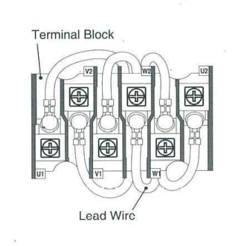
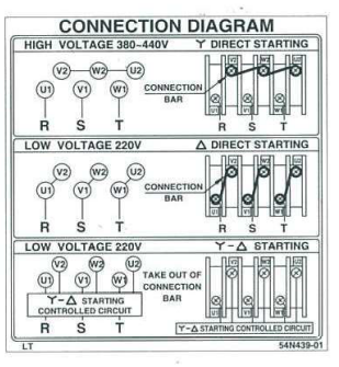
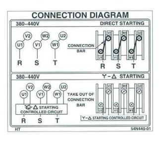
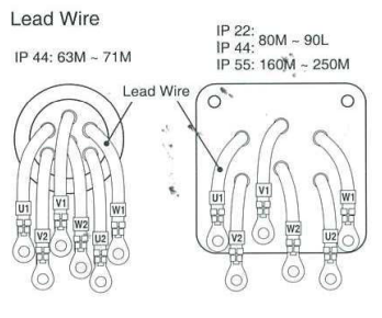
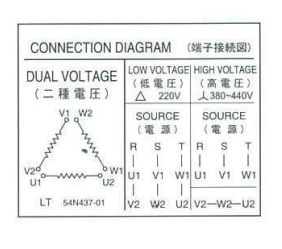
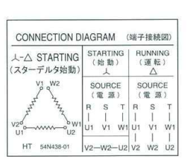
Connection
| Construction of Lead Wires | Connection Diagram | |||||||
| LT | HT * | |||||||
 |
 |
 |
||||||
 |
 |
 |
||||||
* HT can be used only with motors 5HP and above